
Non-valve filter with double filter layers

A valveless filter, double filter layer technology, applied in the field of water treatment, can solve the problems of short replacement cycle, difficult to meet the effluent, sand running, etc., to achieve the effect of improving effluent quality, high interception efficiency and convenient management

Inactive Publication Date: 2014-08-06
TONGJI UNIV
View PDF11 Cites 4 Cited by
  • Summary
  • Abstract
  • Description
  • Claims
  • Application Information

AI Technical Summary

Problems solved by technology

However, for the valveless filter, due to the thin filter layer, the traditional filter material quartz sand is easy to plate, the replacement cycle is short, and the sand runs out during backwashing, etc., resulting in low filtration efficiency and difficult water discharge in the valveless filter. Meet the requirements of "Drinking Water Sanitation Standard" (GB5749-2006)

Method used


Image

  • Non-valve filter with double filter layers
  • Non-valve filter with double filter layers
  • Non-valve filter with double filter layers

Examples


Embodiment 1

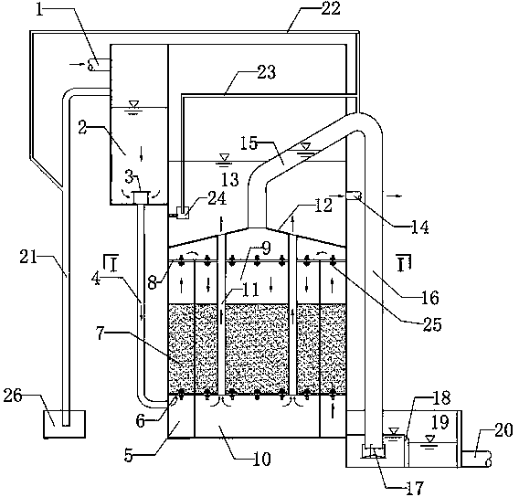
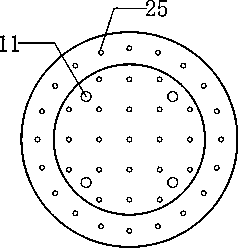
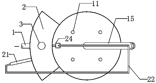
[0020] Such as Figure 1-Figure 3 As shown, the double filter layer valveless filter is composed of water inlet pipe, filter unit and siphon system. Its structure is as follows: figure 1 shown. in:

[0021] The water inlet part is composed of water inlet pipe 1, water distribution tank 2, baffle plate 3, and water inlet branch pipe 4. Two devices can share one water inlet pipe 1, and a baffle plate 3 is provided at the water inlet branch pipe port 4; the function of the baffle plate 3 is to prevent The gas enters the subsequent section.

[0022] The filter unit is a double-layer cylindrical filter tank, which consists of the first water distribution chamber 5, the lower filter plate 6, the ceramsite filter material 7, the upper filter plate 8, the second water distribution chamber 9, the clean water chamber 10, the clean water pipe 11, The filter head 25, the water outlet 14, and the flushing water tank 13 are composed of the homogeneous ceramsite filter material above the ...

Embodiment 2

[0030] Example 2: The raw water is river water in a certain village, and the treatment scale is 100m 3 / d, the front end adopts "grid flocculation + inclined tube precipitation", and the present invention is adopted later, the raw water turbidity is 35NTU, the dosage of polyaluminum chloride is 20mg / L, and the turbidity of the precipitated water is 4NTU, after being filtered by the present invention , The turbidity of the effluent is 0.7NTU.


PUM

PropertyMeasurementUnit
diameteraaaaaaaaaa

Abstract

The invention relates to the technical field of water treatment, and in particular relates to a non-valve filter with double filter layers used for water treatment. The filter comprises a water inlet pipe, a filter unit and a siphon system, wherein the water inlet pipe is located at the left upper part of the filter; a baffle is arranged at the opening of the water inlet branch pipe; homogeneous ceramsite filter material is located above a lower filter plate; an upper filter plate is located under a top cover; four clear water pipes run through the upper and lower filter plates and the filter material; a first water distribution chamber is located between the outer wall of the filter and the inner ring; a second water distribution chamber is located in an inner ring of the filter and above the filter material; a clear water chamber is located in the inner ring and under the lower filter plate; a water outlet is located at the right side of a flushing tank; the flushing tank is communicated with the clear water pipes; a siphon rising pipe is connected with a siphon down pipe and communicated with a top cover of the filter unit; the end of the siphon down pipe is provided with a washing intensity regulator and immersed in a drainage weir; a siphon break funnel is located at the left upper part of the flushing tank and connected with a siphon break pipe; an exhaust pipe and a siphon auxiliary pipe are located at the left side of the filter. The filter realizes automation of whole process of filtering and back flushing, is simple in operation, and is economical and practical.

Description

technical field [0001] The invention belongs to the technical field of water treatment, and in particular relates to a double filter layer valveless filter for water treatment. Background technique [0002] With the development of the economy and the increase of the population, water resources are in short supply in many areas, and some urban drinking water sources are seriously polluted, and the safety of drinking water for residents is threatened. The "Drinking Water Sanitation Standard" (GB5749-85) issued in 1985 can no longer meet the needs of safeguarding the health of the people. To this end, the state issued a new "Drinking Water Hygienic Standards" (GB5749-2006). Compared with the old standard, the new standard adds 11 new indicators, and some indicators have stricter restrictions. Higher standards mean better handling techniques and workmanship. However, in relatively backward and remote areas such as rural areas and mountainous areas, traditional gravity valvele...

Claims


Application Information

Patent Timeline
Patent Type & Authority Applications(China)
IPC IPC(8): B01D24/18B01D24/46
Inventor 徐扬舸庞维海王丝可何秋颖尹大强杨殿海
Owner TONGJI UNIV
Learn More