
Lithium ion secondary battery and method for manufacturing same

A secondary battery and manufacturing method technology, applied in the direction of secondary battery, electrolyte storage battery manufacturing, electrode manufacturing, etc., can solve the problems of shortening battery life, battery performance degradation, etc., and achieve the effect of improving charge-discharge cycle characteristics

Active Publication Date: 2014-07-16
TOYOTA JIDOSHA KK
View PDF5 Cites 0 Cited by
  • Summary
  • Abstract
  • Description
  • Claims
  • Application Information

AI Technical Summary

Problems solved by technology

[0003] In Patent Document 1, as a conventional problem, it is described that in a conventional lithium-ion secondary battery, if the lithium-ion secondary battery is repeatedly charged and discharged, LiPF used as a non-aqueous electrolyte 6 The LiF produced by the side reaction of LiF is irregularly formed on the surface of the negative electrode made of carbon, which reduces the performance of the battery and shortens the life of the battery (paragraph [0004])

Method used


Image

  • Lithium ion secondary battery and method for manufacturing same
  • Lithium ion secondary battery and method for manufacturing same
  • Lithium ion secondary battery and method for manufacturing same

Examples


Embodiment

[0101] Examples and comparative examples related to the present invention will be described.

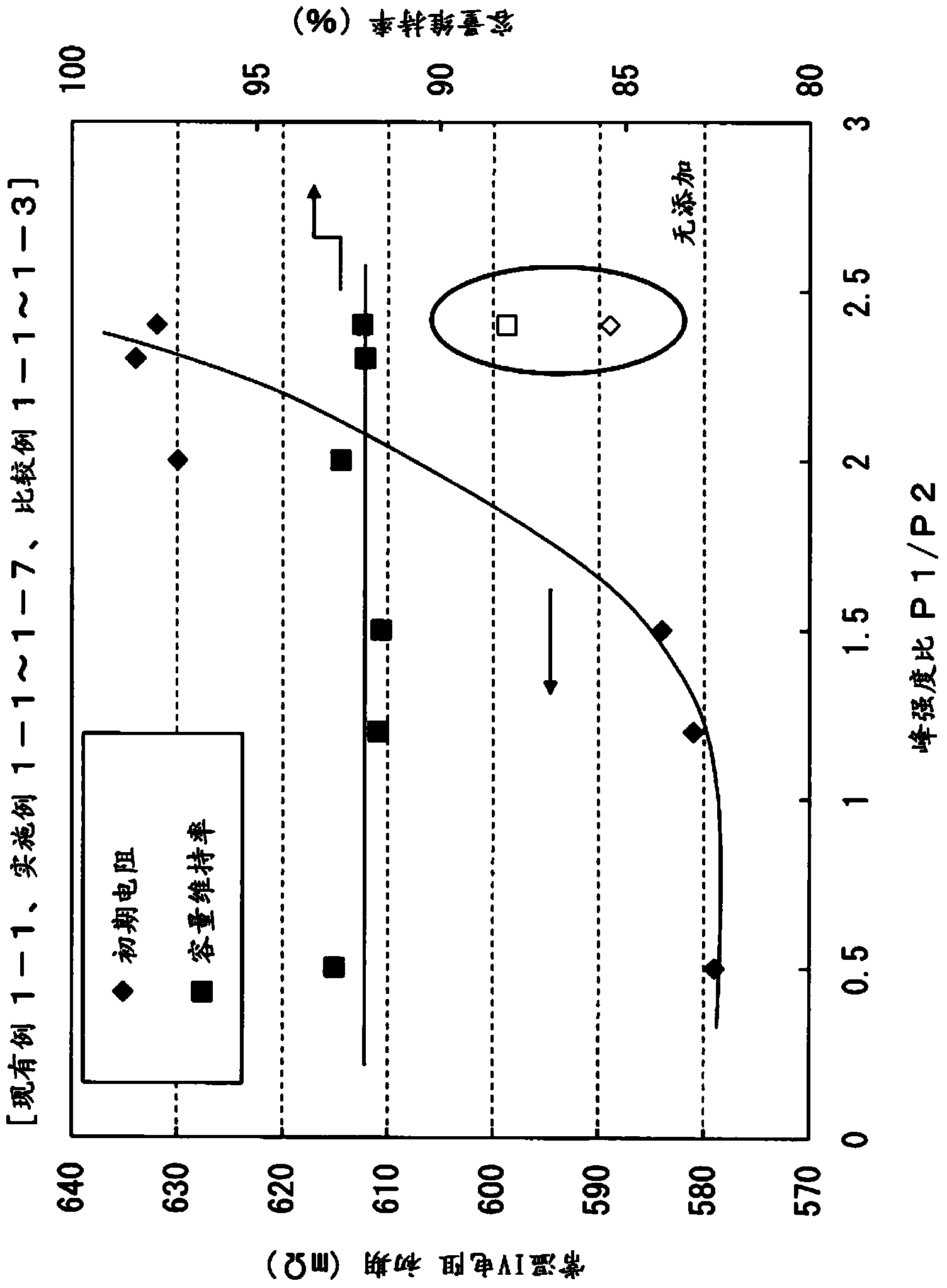
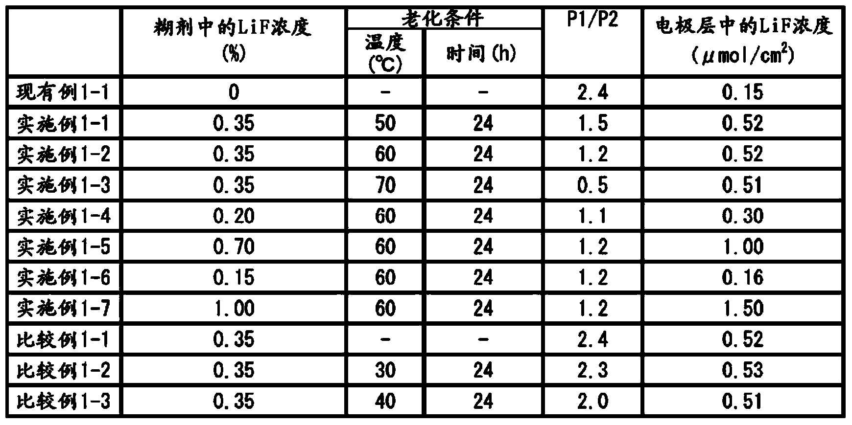
[0102] [Conventional Example 1-1, Examples 1-1 to 1-7, Comparative Examples 1-1 to 1-3]

[0103] In Conventional Example 1-1, Examples 1-1 to 1-7, and Comparative Examples 1-1 to 1-3, samples were prepared and evaluated by adding lithium fluoride to the negative electrode active material.

[0104]

[0105] Using the general formula LiMn 1 / 3 co 1 / 3 Ni 1 / 3 o 2 The ternary lithium composite oxide shown is used as the positive electrode active material. The specific surface area of ​​the positive electrode active material is 1.3m 2 / g.

[0106] In each example, N-methyl-2-pyrrolidone was used as a dispersant, and the above positive electrode active material, acetylene black as a conductive agent, and PVDF as a binder were mixed to obtain a paste for electrode layer formation.

[0107] In each example, the mass ratio of the positive electrode active material, the conductive agent...

Embodiment 2-1~2-7

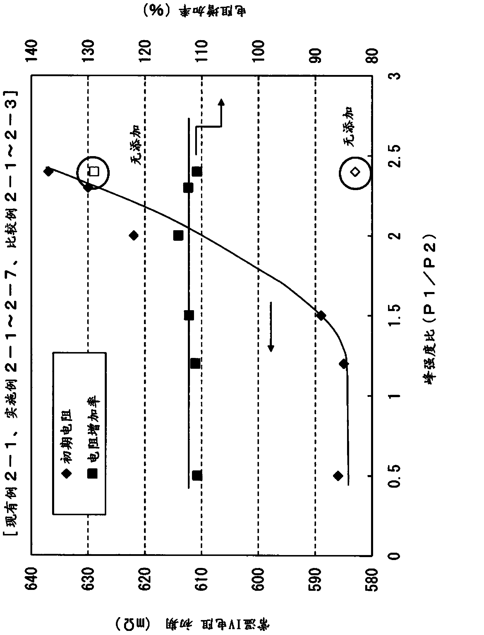
[0152] [Conventional Example 2-1, Examples 2-1 to 2-7, Comparative Examples 2-1 to 2-3]

[0153] In Conventional Example 2-1, Examples 2-1 to 2-7, and Comparative Examples 2-1 to 2-3, samples were produced and evaluated for the addition of lithium fluoride to the positive electrode active material.

[0154]

[0155] Using the general formula LiMn 1 / 3 co 1 / 3 Ni 1 / 3 o 2 The ternary lithium composite oxide shown is used as the positive electrode active material. The specific surface area of ​​the positive electrode active material is 1.3m 2 / g.

[0156]In Examples 2-1 to 2-7 and Comparative Examples 2-1 to 2-3, N-methyl-2-pyrrolidone was used as a dispersant, and the above-mentioned positive electrode active material, lithium fluoride, and acetylene as a conductive agent were mixed. black, and PVDF as a binder to obtain a paste for electrode layer formation.

[0157] Table 3 shows the lithium fluoride concentration (mass %) in the solid content of the paste for electrode...


PUM

PropertyMeasurementUnit
specific surface areaaaaaaaaaaa
densityaaaaaaaaaa
specific surface areaaaaaaaaaaa

Abstract

The present invention provides: a lithium ion secondary battery which is able to have improved charge and discharge cycle characteristics or improved durability such as high-temperature storage endurance characteristics, while suppressing deterioration in the initial performance; and a method for manufacturing the lithium ion secondary battery. This lithium ion secondary battery comprises an electrode that is a positive electrode or negative electrode which is provided with an electrode layer containing an active material. At least a part of the surface of the active material is covered with a lithium halide (X) having low ion binding properties, said lithium halide (X) having a ratio of the peak intensity (P1) near 60 eV to the peak intensity (P2) near 70 eV in an Li-XAFS measurement, namely a peak intensity ratio P1 / P2 of less than 2.0.

Description

technical field [0001] The present invention relates to an electrode for a lithium ion secondary battery and a manufacturing method thereof. Background technique [0002] Lithium-ion secondary batteries are roughly composed of a positive electrode containing active materials such as Li-containing composite oxides, a negative electrode containing active materials such as carbon, a separator that insulates them, and a lithium-ion battery containing LiPF. 6 and other non-aqueous electrolytes. [0003] In Patent Document 1, as a conventional problem, it is described that in a conventional lithium-ion secondary battery, if the lithium-ion secondary battery is repeatedly charged and discharged, LiPF used as a non-aqueous electrolyte 6 The LiF generated by the side reaction of LiF is irregularly formed on the surface of the negative electrode made of carbon, which reduces the performance of the battery and shortens the life of the battery (paragraph [0004]). [0004] Patent Docum...

Claims


Application Information

Patent Timeline
Patent Type & Authority Applications(China)
IPC IPC(8): H01M4/587H01M4/36H01M4/505H01M4/525H01M10/052H01M10/058
CPCH01M4/1391H01M4/366H01M4/505H01M4/525H01M4/582H01M4/62H01M10/0525H01M2004/021H01M4/0447H01M4/0471H01M4/131H01M4/133H01M4/587H01M10/049H01M10/052H01M10/0567H01M10/446Y02E60/10Y02P70/50B05D3/007B05D3/10B05D3/107H01M4/485H01M4/502H01M4/628H01M2004/027Y02T10/70
Inventor 鬼冢宏司坂野充中野智弘
Owner TOYOTA JIDOSHA KK
Learn More