
Two-phase interleaved converter based on coupled inductors

A technology of coupled inductors and converters is applied in the field of two-phase interleaved parallel converters, which can solve the problem of insufficient height and achieve the effects of high boosting ratio, reducing loss and improving conversion efficiency.

Active Publication Date: 2014-07-16
浙江品川信息技术有限公司
View PDF8 Cites 18 Cited by
  • Summary
  • Abstract
  • Description
  • Claims
  • Application Information

AI Technical Summary

Problems solved by technology

Compared with the traditional interleaved parallel BOOST converter, the voltage gain of this application is improved, but it is still not high enough

Method used


Image

  • Two-phase interleaved converter based on coupled inductors

Examples


Embodiment 1

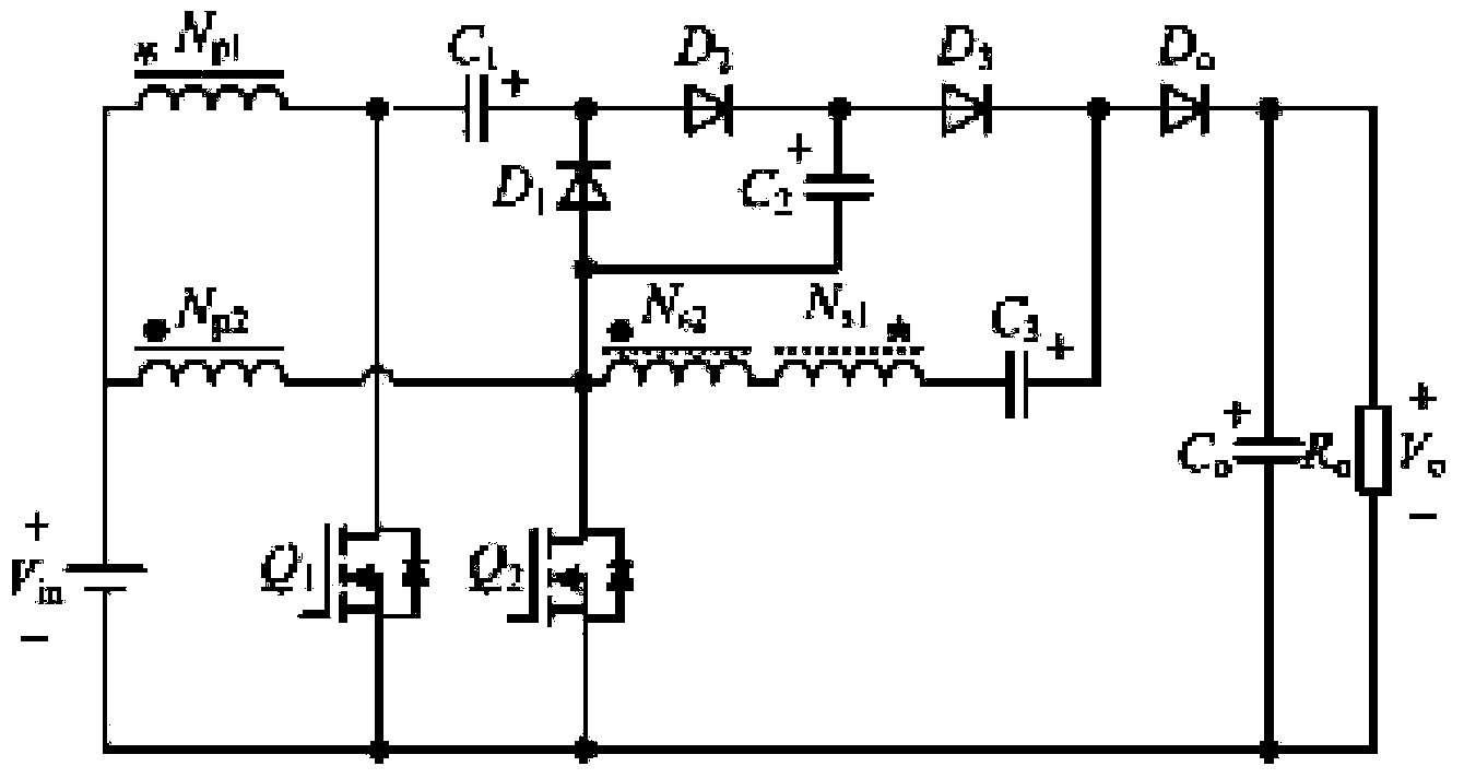
[0021] As shown in Figure 1, 1. A two-phase interleaved parallel converter based on coupled inductors, characterized in that it includes a DC input source V in , the first power switch Q 1 , the second power switch Q 2 , with the first winding N p1 and the second winding N s1 The first coupled inductor, with a third winding N p2 and the fourth winding N s2 The second coupled inductor, the first unidirectional rectifier diode D 1 , the second unidirectional rectifier diode D 2 , the third unidirectional rectifier diode D 3 , the output diode D o , the clamp capacitor C 1 , the first intermediate storage capacitor C 2 , the second intermediate storage capacitor C 3 and output filter capacitor C o ;

[0022] The first winding N of the first coupled inductor p1 The dotted end of the third winding N with the second coupled inductor p2 The eponymous terminal of the DC input source V in The anode of the first coupled inductor is connected to the first winding N p1 The...


PUM


Abstract

The invention discloses a topological structure of a two-phase interleaved converter based on coupled inductors and belongs to the technical field of the power and electron technology. The two-phase interleaved converter based on the coupled inductors comprises a direct-current input source, two power switch tubes, the two coupled inductors with two windings, three one-way rectifier diodes, an output diode, a clamping capacitor, two intermediate energy-storage capacitors and an output filter capacitor. According to the two-phase interleaved converter based on the coupled inductors, the boosting capacity is high, output with a higher step-up ratio can be achieved, and stress of the peak voltage of the power switch tubes and stress of the peak voltage of the diodes are reduced to a certain extent; meanwhile, zero-current switching-on of the power switch tubes and turning-off the diodes are achieved through the leakage inductance of the coupled inductors, in this way, the conversion efficiency of a whole conversion circuit is improved, and input current ripples are reduced due to the adoption of a two-phase interleaved control method.

Description

technical field [0001] The invention relates to a DC-DC converter in the field of power electronics, in particular to a two-phase interleaved parallel converter based on coupled inductance. Background technique [0002] With the DC-DC boost converter receiving more and more attention in the field of grid-connected power generation systems such as photovoltaics and fuel cells, the research on its related application technology has also increased. The output voltage gain of the traditional two-phase interleaved parallel BOOST converter is small, the voltage stress of the power switch is large, and the switching loss is large. For this reason, the method of using soft switching circuit has appeared one after another. Although the soft switching of the power switching tube can be realized, the voltage stress of the power switching tube cannot be reduced; The voltage requires a large number of switched capacitors, and the structure is complex. In order to increase the voltage o...

Claims


Application Information

Patent Timeline
Patent Type & Authority Applications(China)
IPC IPC(8): H02M3/07
Inventor 胡雪峰王琳章家岩张纯
Owner 浙江品川信息技术有限公司
Learn More