
Online oil liquid abrasive particle monitoring device and measuring method

A monitoring device and technology of oil abrasive particles, applied in the direction of material resistance, etc., can solve the problems that cannot meet the needs of abrasive particle technology, the abrasive particle detection process is not suitable, the imaging speed is slow and online detection cannot be realized, etc.

Inactive Publication Date: 2014-07-16
TIANJIN UNIV
View PDF9 Cites 24 Cited by
  • Summary
  • Abstract
  • Description
  • Claims
  • Application Information

AI Technical Summary

Problems solved by technology

[0011] Although the above-mentioned electrical tomography method can realize imaging, there are also unsuitable aspects in the process of wear particle detection.
First of all, the imaging speed of this method is too slow to realize online detection; secondly, electrical tomography technology has developed maturely in the field of medical equipment, and is mostly used in common-sized laboratories or portable on-site diagnostics such as human body imaging and multiphase flow imaging in pipelines. The online detection of abrasive particles has not been realized; in addition, this method does not calculate the number of abrasive particles, the shape of abrasive particles, the size of abrasive particles, and the material of abrasive particles in the detection and identification of abrasive particles, which cannot meet the requirements of online detection of abrasive particles. technical needs

Method used


Image

  • Online oil liquid abrasive particle monitoring device and measuring method
  • Online oil liquid abrasive particle monitoring device and measuring method
  • Online oil liquid abrasive particle monitoring device and measuring method

Examples


Embodiment Construction

[0065] In order to make the purpose, technical solution and advantages of the present invention clearer, the implementation manners of the present invention will be further described in detail below.

[0066] Such as figure 1 As shown, the online oil wear particle monitoring device in the embodiment of the present invention includes: an online multi-electrode tomography wear particle sensor 1, an excitation signal source circuit 2, a signal detection filter circuit 3, an analog-to-digital conversion circuit 4, a computer 5, Display 6 and keyboard 7.

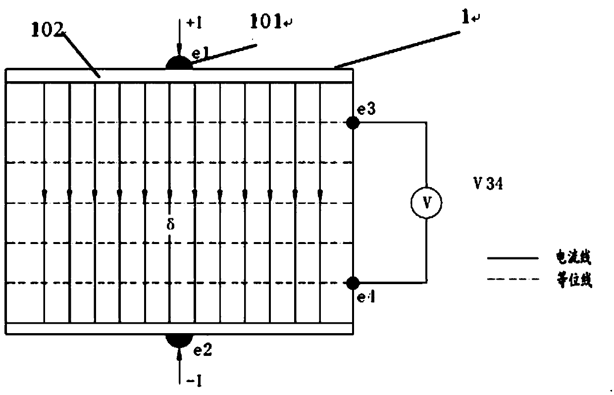
[0067] Among them, the online multi-electrode tomography wear particle sensor 1 is a composite array sensor of the electrical tomography system that can be connected to the oil pipeline online, and is a sensor for the purpose of realizing impedance imaging. It consists of a certain number of electrodes 101 constitute. The plurality of electrodes 101 are realized by thick resist lithography technology (thick resist lithography t...


PUM


Abstract

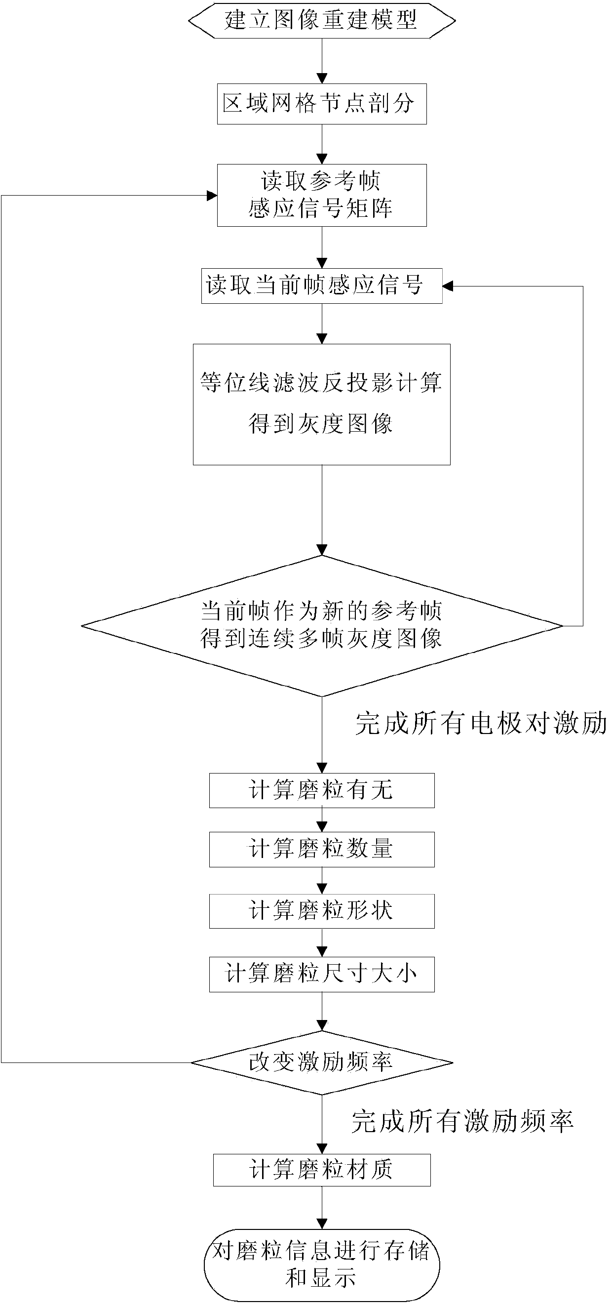
The invention discloses an online oil liquid abrasive particle monitoring device and measuring method. The online oil liquid abrasive particle monitoring device comprises an online multi-electrode chromatography imaging abrasive particle sensor, a photoelectric isolation module, an exciting part circuit, a measuring part circuit, power sources, a signal filtering circuit, an AD (Analog / Digital) conversion circuit and a signal path, wherein the power sources are used by the exciting part circuit and the measuring part circuit, respectively, and the signal path adopts fully differential signal transmission. The measuring method comprises the following steps: pre-processing a software phase wave measuring signal; rebuilding an image model according to a finite element rule; reading a frame induction signal; calculating equipotential line filtering reverse projection to generate a gray image; generating a continuous multi-frame image; calculating the count, sizes and shapes of abrasive practices; generating a multi-frequency gray image and calculating the textures of the abrasive practices; and storing and displaying abrasive particle information which represents the abrasive particle information in oil liquid and the abrasion state of a device. According to the online oil liquid abrasive particle monitoring device and the measuring method, both metallic and non-metallic particles can be measured and the count, sizes, shapes and varieties of the abrasive particles can be quantitatively measured.

Description

technical field [0001] The invention relates to the field of on-line monitoring of the wear state of a machine system, in particular to an on-line oil abrasive particle monitoring device and a detection method. Background technique [0002] On-line oil monitoring is an important method for early fault detection of mechanical equipment. The real-time oil analysis sensor is an oil analysis instrument. It detects the operation of mechanical equipment in real time by detecting the size, quantity, material and shape of abrasive particles in the oil, and timely predicts potential failures to avoid catastrophic damage or use. Equipment in normal operation reduces unnecessary maintenance, thereby increasing production value and profitability. [0003] In the prior art, there is disclosed an online oil circuit wear monitoring device (public number: CN 103217365 A), by adjusting the amplitude difference and sum of the excitation signals on the two sets of excitation coils of the oil ...

Claims


Application Information

Patent Timeline
IPC IPC(8): G01N27/06
Inventor 孙衍山曾周末张涛李健靳世久
Owner TIANJIN UNIV
Learn More