
Apparatus for removing photoresist at edge of substrate

A technology of edge light and photoresist, which is applied in the direction of spraying device, spraying device, photosensitive material processing, etc., can solve the problems of photoresist dissolver blowing to the substrate, photoresist dissolver being resisted, splashing, etc. Achieve the effect of avoiding sputtering into the substrate, avoiding substrate defects, and reducing defective points

Inactive Publication Date: 2014-07-09
BOE TECH GRP CO LTD +1
View PDF7 Cites 3 Cited by
  • Summary
  • Abstract
  • Description
  • Claims
  • Application Information

AI Technical Summary

Problems solved by technology

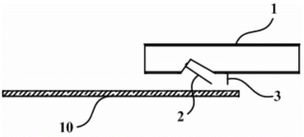
However, in the process of removing the photoresist at the edge of the substrate, the pinhole of the needle nozzle is too thin, it is easy to block after foreign matter enters, and it is also easy to deform when encountering an external force. After the gas nozzle is blocked or deformed, the photoresist dissolver cannot be blown to the substrate in time. In addition, after the liquid nozzle is blocked or deformed, the resistance of the photoresist dissolver is too large when sprayed, and splashing is more likely to occur
Moreover, when the photoresist dissolving agent is sputtered to the position inside the substrate where the photoresist does not need to be removed, the photoresist at this position is dissolved, and the film layer at this position is etched away in the subsequent etching process, and then Defective spots are formed on the substrate, resulting in defective panels

Method used


Image

  • Apparatus for removing photoresist at edge of substrate
  • Apparatus for removing photoresist at edge of substrate
  • Apparatus for removing photoresist at edge of substrate

Examples


Embodiment Construction

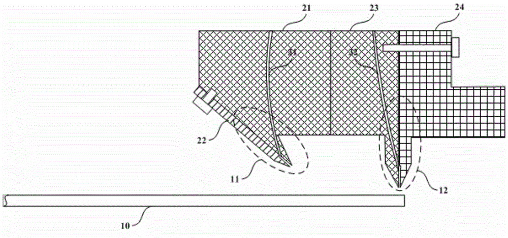
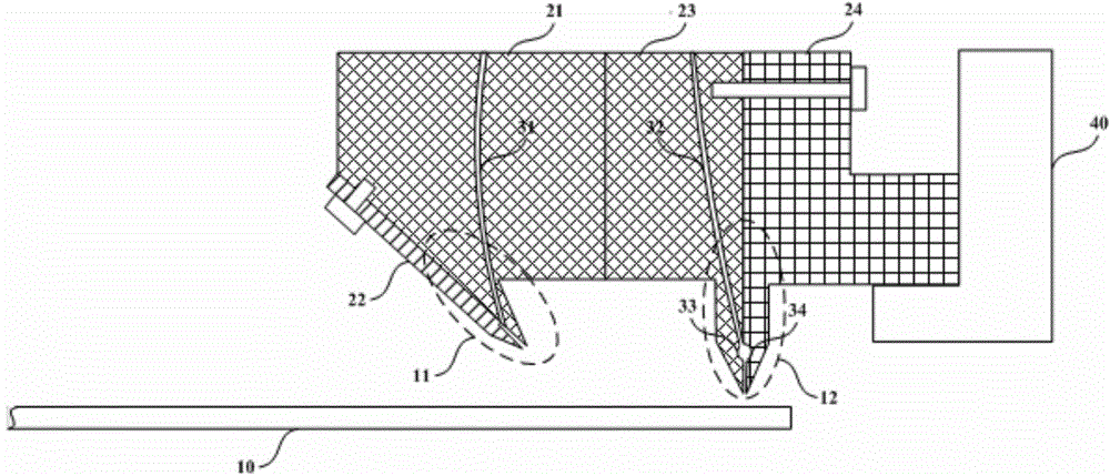
[0033] In order to effectively prevent nozzle clogging, an embodiment of the present invention provides a device for removing photoresist at the edge of a substrate. In this technical solution, due to the use of slit-shaped gas nozzles or slit-shaped liquid nozzles, compared with the existing needle-shaped nozzles, it is not easy to be blocked, and it is easier to eject gas or liquid smoothly, and will not cause the photoresist dissolver to be damaged. Sputtering occurs due to blockage or deformation of the needle-shaped nozzle, which avoids the occurrence of defective substrates caused by sputtering photoresist dissolvers inside the substrate. In order to make the purpose, technical solution and advantages of the present invention clearer, the following specific examples are given to further describe the present invention in detail.

[0034] An embodiment of the present invention provides a device for removing photoresist at the edge of a substrate, such as figure 2 as show...


PUM

PropertyMeasurementUnit
Slit widthaaaaaaaaaa
Spacingaaaaaaaaaa

Abstract

The invention relates to the technical field of an apparatus for removing a photoresist, and discloses an apparatus for removing the photoresist at edge of a substrate. The apparatus for removing the photoresist at edge of the substrate comprises a spray washing apparatus, the spray washing apparatus comprises a liquid nozzle for injecting a photoresist solvent and a gas nozzle for injecting gas, gas injected from the gas nozzle blows the photoresist solvent at the edge of the substrate to the outer side of the substrate, the gas nozzle and the liquid nozzle are respectively the slit-shape gas nozzle and the slit-shape liquid nozzle; the gas injected from the slit-shape gas nozzle is fallen on the surface of the substrate to form a first slit zone, the liquid injected from the slit-shape liquid nozzle is fallen on the surface of the substrate to form a second slit zone, and the first slit zone and the second slit zone are not overlapped. According to the technical scheme, by employing the slit-shape gas nozzle or the slit-shape liquid nozzle, gas or liquid is smoothly injected, sputtering of the photoresist solvent can be avoided, and the generation of the adverse phenomenon of the substrate due to sputtering of the photoresist solvent in the substrate can be avoided.

Description

technical field [0001] The invention relates to the technical field of photoresist removal equipment, in particular to a device for removing photoresist at the edge of a substrate. Background technique [0002] Among the flat panel display devices, Thin Film Transistor Liquid Crystal Display (TFT-LCD) has the characteristics of small size, low power consumption, relatively low manufacturing cost and low radiation, and occupies a dominant position in the current flat panel display market. leading position. [0003] In the manufacturing process of TFT-LCD, the array process (Array) mainly consists of three major processes, namely deposition (Deposition) process, mask (Mask) process and etching (Etch) process. In the masking process, a layer of photoresist (Photo Resist, also known as photoresist) is uniformly coated on the substrate that has undergone the deposition process, and the thin film transistor pattern (TFT -pattern), and finally through the etching process to etch ...

Claims


Application Information

Patent Timeline
IPC IPC(8): G03F7/42B05B1/02B05B15/02B05B15/04
Inventor 宋蓬磊王晏酩焦宇高安安何继业宋玉冰
Owner BOE TECH GRP CO LTD
Learn More