
Circuit board and manufacturing method thereof

A manufacturing method and circuit board technology, which is applied in the directions of printed circuit components, electrical connection printed components, and printed component electrical connection formation, etc., which can solve the problems of increased difficulty in alignment, excessive aspect ratio, and increased wiring area of ​​printed circuit boards, etc. , to achieve the effect of improving alignment ability and quality

Active Publication Date: 2017-04-12
NAN YA PRINTED CIRCUIT BOARD CORPORATION
View PDF5 Cites 0 Cited by
  • Summary
  • Abstract
  • Description
  • Claims
  • Application Information

AI Technical Summary

Problems solved by technology

However, since the aspect ratio of the via hole connected to the conductive pad is too high, it will increase the difficulty of the process and cause defects in the printed circuit board, so that the size reduction of the via hole has reached a bottleneck.
Furthermore, when the size of the conductive pad is reduced, it will increase the difficulty of alignment in the process, and it is difficult to increase the available wiring area on the printed circuit board in a limited space.

Method used


Image

  • Circuit board and manufacturing method thereof
  • Circuit board and manufacturing method thereof
  • Circuit board and manufacturing method thereof

Examples


Embodiment Construction

[0041] The circuit board of the embodiment of the present invention and its manufacturing method are described below. However, it can be easily understood that the embodiments provided in the present invention are only used to illustrate the making and use of the present invention in a specific way, and are not intended to limit the scope of the present invention. Furthermore, the same reference numerals are used in the drawings and descriptions of the embodiments of the present invention to denote the same or similar components.

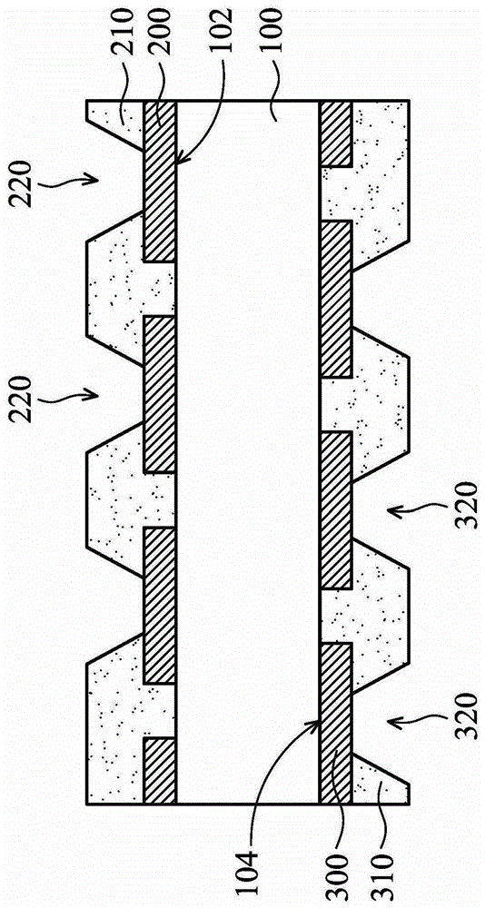
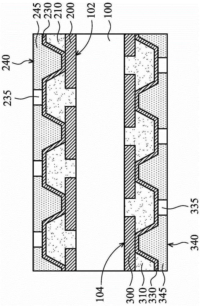
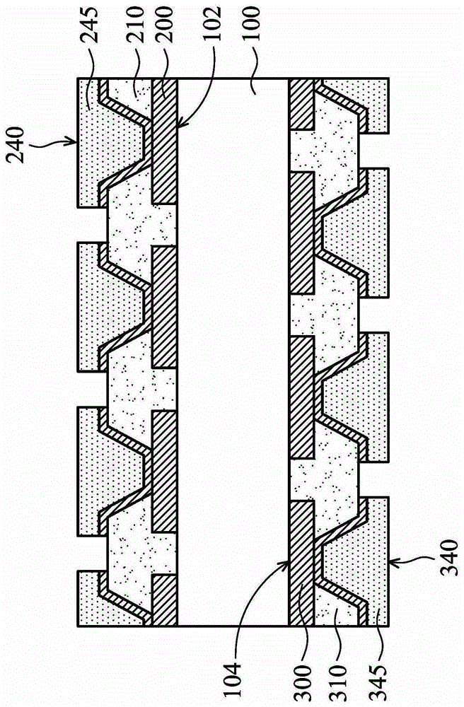
[0042] Please refer to Figure 6 , which shows a schematic cross-sectional view of a circuit board according to an embodiment of the present invention. In this embodiment, the circuit board includes a substrate 100, a plurality of first conductive blocks 200, a first insulating layer 210, a plurality of first conductive components 240, a second insulating layer 250, a second conductive component 280, a plurality of A second conductive block 300 , ...


PUM


Abstract

The invention discloses a circuit board and a manufacturing method. The circuit board comprises a substrate. A first insulation layer is disposed on the substrate, and is provided with a plurality of first openings. A plurality of first conductive parts are disposed on the first insulation layer at intervals, and are correspondingly disposed in the first openings in a filled manner. A second insulation layer is disposed on the first insulation layer, and is provided with a plurality of second openings to expose the first conductive parts. A plurality of second conductive parts are disposed on the second insulation layer at intervals, and are disposed in the second openings in a filled manner. The second openings are smaller than the first openings. The invention is advantageous in that the counterpoint ability of the technique can be improved, and the wiring area, the transmission speed, and the transmission direction of the printed circuit board in the limited space can be increased, and the high density requirement can be satisified. The difficulty of the laser drilling, the resin smear removal or the electroplating techniques can be reduced, the possibility of faults can be reduced, and the quality of the printed circuit board can be improved.

Description

technical field [0001] The invention relates to a circuit board technology, in particular to a circuit board with small-sized conductive pads and a manufacturing method thereof. Background technique [0002] A printed circuit board (PCB) is a circuit board in which electrical conductors are formed on insulators by means of mechanical and chemical processing, surface treatment, etc., according to circuit design, drawing wiring patterns for conductive wiring connecting circuit parts. The above-mentioned circuit pattern is formed by printing, photolithography, etching, electroplating and other technologies to form precise wiring, and serves as an assembly platform for supporting electronic components and interconnecting circuits between components. [0003] With the continuous development of electronic products in the direction of light, thin, short, small and multi-functional, the size of the chip is gradually reduced, and the number of input and output (I / O) increases, result...

Claims


Application Information

Patent Timeline
Patent Type & Authority Patents(China)
IPC IPC(8): H05K1/11H05K3/40
Inventor 黄振宏
Owner NAN YA PRINTED CIRCUIT BOARD CORPORATION
Learn More