
Low-temperature-coefficient variable gain amplifier for enlarging gain change range

A low temperature coefficient, gain amplifier technology, applied in single-ended push-pull amplifiers, improving amplifiers to reduce temperature/power supply voltage changes, etc., can solve problems such as increasing gain adjustment range, limited single-stage gain, and increased circuit power consumption , to improve the transconductance current efficiency, increase the gain adjustment range, and achieve the effect of low common mode gain

Inactive Publication Date: 2014-07-02
SOUTHEAST UNIV
View PDF6 Cites 8 Cited by
  • Summary
  • Abstract
  • Description
  • Claims
  • Application Information

AI Technical Summary

Problems solved by technology

The variable gain amplifier with low temperature coefficient that improves the gain range is widely used because of its continuous gain change and no phase mutation. The traditional variable gain amplifier with low temperature coefficient that increases the gain range is limited by the single-stage gain. The gain adjustment range often adopts multi-stage cascading methods, but these methods increase the gain adjustment range and the circuit power consumption will also increase significantly, and the gain adjustment range is significantly affected by temperature
Therefore, there are still many challenges to improve the gain adjustment range of a single-stage variable gain amplifier without increasing power consumption, and to ensure that the circuit can work normally in harsh environments.

Method used


Image

  • Low-temperature-coefficient variable gain amplifier for enlarging gain change range
  • Low-temperature-coefficient variable gain amplifier for enlarging gain change range
  • Low-temperature-coefficient variable gain amplifier for enlarging gain change range

Examples


Embodiment Construction

[0045] Below in conjunction with accompanying drawing and specific embodiment the present invention is described in further detail:

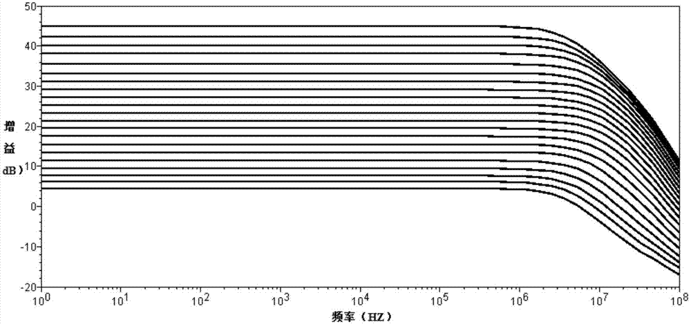
[0046] see figure 1 As shown, the low temperature coefficient variable gain amplifier of the present invention, which improves the range of gain variation, includes a variable gain circuit, a cross-coupling temperature compensation circuit and a gain control circuit.

[0047] Wherein, the variable gain circuit includes a first P-type metal oxide transistor P1, a second P-type metal oxide transistor P2, a first N-type metal oxide transistor N1, a second N-type metal oxide transistor N2, a third N NMOS transistor N3, fourth NMOS transistor N4, fifth NMOS transistor N5, sixth NMOS transistor N6, seventh NMOS transistor N7, eighth NMOS transistor NMOS transistor N8, ninth NMOS transistor N9, tenth NMOS transistor N10, eleventh NMOS transistor N11, twelfth NMOS transistor N12, The thirteenth NMOS transistor N13 , the fourteenth NMOS transistor N14 ...


PUM


Abstract

The invention discloses a low-temperature-coefficient variable gain amplifier for enlarging the gain change range. The low-temperature-coefficient variable gain amplifier for enlarging the gain change range comprises a variable gain circuit, a cross coupling temperature compensation circuit and a gain control circuit, wherein the variable gain circuit adjusts the circuit gain according to the intensity of an input signal to stabilize the output power, a negative resistor is adopted to serve as a source electrode degeneration resistor to form positive feedback to improve the transconductance current efficiency of the input transconductance level, a transistor pair connected with a diode and a transistor pair connected with a cross coupler form an active load, under the condition of different-mode signals, a cross coupler pair serves as a negative conductor to reduce the overall conductance of the load, the common-mode gain of the circuit is very low, the cross coupler pair not only improves the gain of the circuit, but also improves the common-mode rejection capacity of the circuit, and meanwhile the cross coupler pair and a reference source with the positive temperature characteristic form the temperature compensation circuit to compensate for the gain range changes of the variable gain circuit caused by temperature changes. The low-temperature-coefficient variable gain amplifier for enlarging the gain change range has the advantages of being large in single-level gain adjusting range, resistant to technological changes, resistant to temperature changes, low in energy consumption and the like.

Description

technical field [0001] The invention relates to a variable gain amplifier with low temperature coefficient that improves the range of gain variation. Background technique [0002] As a key module of wireless receiver, variable gain amplifier has been a research hotspot in radio frequency and analog integrated circuits. In a wireless communication system, due to changes in the external environment such as temperature, obstacles, etc., the signal strength received by the receiver varies greatly. If the receiver signal link gain is constant, the large signal will be blocked when receiving a large signal. If Received very weak signals are easily submerged by noise and cannot be demodulated, so the gain of the receiver is required to be automatically adjusted according to the strength of the signal, that is, when the received signal is strong, the gain of the receiver is reduced, and when the received signal is weak, the receiver Gain, this function is mainly done by the variabl...

Claims


Application Information

Patent Timeline
Patent Type & Authority Applications(China)
IPC IPC(8): H03F1/30H03F3/30
Inventor 吴建辉赵超陈超李红黄成
Owner SOUTHEAST UNIV
Learn More