Passive filter circuit and transmitting circuit

A passive filter and circuit technology, applied in electrical components, multi-terminal pair networks, impedance networks, etc., can solve problems such as difficulty in reaching the gain range and large differences in gain range.

Active Publication Date: 2021-12-21
SPREADTRUM COMM (SHANGHAI) CO LTD
View PDF13 Cites 0 Cited by
  • Summary
  • Abstract
  • Description
  • Claims
  • Application Information

AI Technical Summary

Problems solved by technology

[0003] However, the gain control of the transmitting circuit in the prior art needs to be realized by radio frequency (Radio Frequency, RF) technology
Then, the gain step of capacitive voltage division technology will change with the change of radio frequency, so that the gain range of different frequency bands is very different; in addition, from the perspective of layout design (layout), the coupling of radio frequency is stronger, There is coupling between the inductors and the wiring, and it is difficult to achieve a gain range of 78dB in practice

Method used


Image

  • Passive filter circuit and transmitting circuit
  • Passive filter circuit and transmitting circuit
  • Passive filter circuit and transmitting circuit

Examples


Embodiment Construction

[0027] As mentioned in the background, the gain control of the transmitting circuit in the prior art needs to be realized by using a radio frequency (Radio Frequency, RF). Then, the gain step of capacitive voltage division technology will change with the change of radio frequency, so that the gain range of different frequency bands is very different; in addition, from the perspective of layout design (layout) implementation, radio frequency coupling (coupling) is stronger, There is coupling between the inductors and the wiring, and it is difficult to achieve a gain range of 78dB in practice.

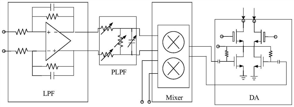
[0028] Please refer to figure 1 , figure 1 It is a structural schematic diagram of a transmitting circuit in the prior art. As the channel length of the CMOS process becomes smaller, the passive mixer (passive mixer) Mixer is also introduced into the transmitting circuit due to its low power consumption and good noise performance, especially the mobile phone transmitting circuit. The ...


PUM


Abstract

A passive filter circuit and a transmission circuit, the passive filter circuit includes: a first selection circuit whose input terminal is connected to an input signal, the first selection circuit includes a plurality of parallel first selection sub-circuits, each selection sub-circuit The circuit is suitable for being controlled to be turned on to transmit the input signal or controlled to be turned off to stop transmitting the input signal; a second selection circuit, whose input terminal is coupled to the output terminal of the first selection circuit, the second selection circuit The selection circuit includes a plurality of second selection sub-circuits connected in parallel, each second selection sub-circuit is adapted to be controlled to be turned on to pass the output signal of the first selection circuit, or controlled to be turned off to stop passing the first selection circuit. an output signal of the selection circuit; a first capacitor, one end of which is coupled to the output end of the first selection circuit; a first load, one end of which is coupled to the output end of the first selection circuit, and the other end of which is coupled to the output end of the first selection circuit A capacitor at the other end. The technical scheme of the present invention can realize gain control in the passive filter circuit.

Description

technical field [0001] The invention relates to the technical field of integrated circuits, in particular to a passive filtering circuit and a transmitting circuit. Background technique [0002] In a wideband code division multiple access (W-CDMA) transmission (Transmit, TX) circuit, the total gain range is required to exceed 70dB. In order to achieve the required gain range, in the driver amplifier (DA), in addition to controlling the size of the main amplifier tube, current steering (current steering) and capacitive voltage divider (cap divider) technologies are also used to achieve a gain adjustment range of 78dB (Among them, the main amplifier tube can achieve 36dB, the current steering technology can achieve 24dB, and the remaining 18dB can be adjusted by capacitive voltage division technology). [0003] However, the gain control of the transmitting circuit in the prior art needs to be implemented using radio frequency (Radio Frequency, RF) technology. Then, the gain ...

Claims


Application Information

Patent Timeline
Patent Type & Authority Patents(China)
IPC IPC(8): H03H7/52
CPCH03H7/52
Inventor 徐志刚陈作添赖玠玮
Owner SPREADTRUM COMM (SHANGHAI) CO LTD
Why Eureka
Try Eureka