
Fiber reinforce plastic (FRP) reinforced concrete-filled steel tube combination column

A technology of concrete filled steel tubes and composite columns, applied in the field of concrete columns, can solve the problems of reduced bearing capacity, rigidity and stability of components, insufficient strength of concrete, weakened restraint capacity of core concrete, etc. Conducive to the effect of structural earthquake resistance and omitting formwork engineering

Active Publication Date: 2014-07-02
HARBIN ENG UNIV
View PDF11 Cites 18 Cited by
  • Summary
  • Abstract
  • Description
  • Claims
  • Application Information

AI Technical Summary

Problems solved by technology

For large-diameter steel pipe concrete, the bonding problem between steel pipe and concrete will be more prominent. When the diameter of the steel pipe is large, the steel pipe’s ability to restrain the core concrete will be weakened, and the core concrete and steel pipe will separate at the interface or the core concrete will not be dense. Hollow phenomenon, the steel pipe wall is easy to buckle prematurely, the concrete strength cannot be fully exerted, and the bearing capacity, stiffness and stability of the component are reduced, which seriously restricts its service performance and service life

Method used


Image

  • Fiber reinforce plastic (FRP) reinforced concrete-filled steel tube combination column
  • Fiber reinforce plastic (FRP) reinforced concrete-filled steel tube combination column
  • Fiber reinforce plastic (FRP) reinforced concrete-filled steel tube combination column

Examples


Embodiment 1

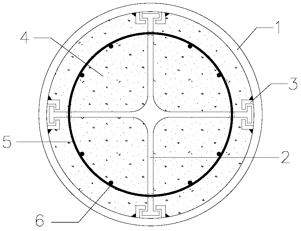
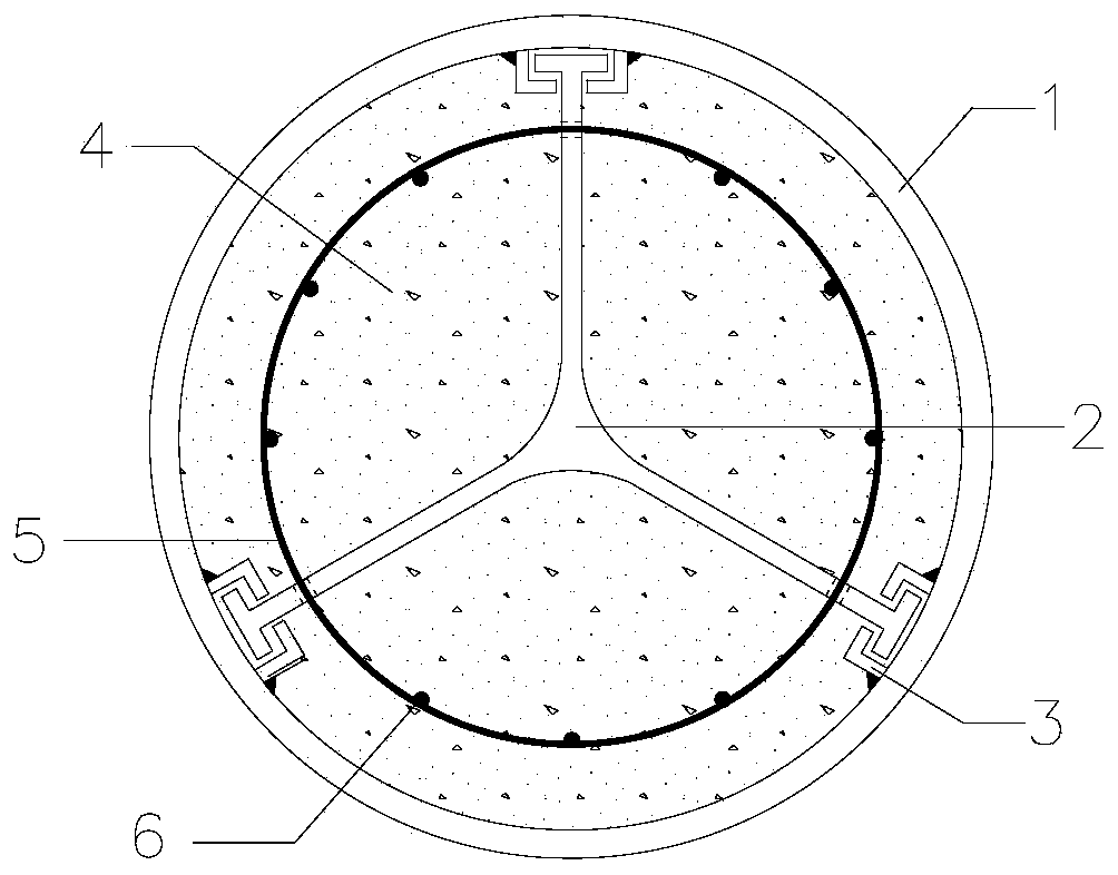
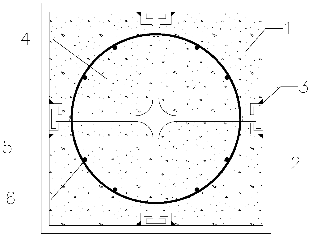
[0028] combine Figure 1~3 , including steel pipe 1, FRP stiffener 2, angle steel 3, concrete 4, stirrup 5 and longitudinal reinforcement 6.

[0029] The structure is formed by mixing concrete 4 with FRP stiffeners 2 with stirrups 5 and longitudinal steel bars 6 and steel pipes 1 . The angle steel 3 is welded to the steel pipe 1, and the welded angle steel forms a pair of two, symmetrically distributed, and the distance between them is determined according to the thickness of the FRP stiffener. For a steel pipe 1 with a larger diameter, it can be directly welded inside the steel pipe 1; for a steel pipe 1 with a small diameter, holes can be drilled at regular intervals on the pipe wall where the steel pipe 1 and the angle steel 3 are connected. The angle steel 3 and the steel pipe 1 are then connected by filling welding. The number of welding points and welding distance can be determined according to calculation. Drill holes at regular intervals along the ring direction on ...

Embodiment 2

[0031] combine Figure 1~3 , including steel pipe 1, FRP stiffener 2, angle steel 3, concrete 4, stirrup 5 and longitudinal reinforcement 6.

[0032] The structure is formed by mixing concrete 4 with FRP stiffeners 2 with stirrups 5 and longitudinal steel bars 6 and steel pipes 1 . For the welding of angle steel 3 and steel pipe 1, half steel pipes can be used, and the angle steel 3 is welded at the designated position respectively, and then the half steel pipes are spliced ​​and welded together, such as Figure 4 , 5 . For square steel pipes, rectangular steel pipes, etc., the angle steel 3 can be welded at the corresponding positions first, and then the steel plates are welded together to form square steel pipes, rectangular steel pipes such as Figure 6 . For the welding of the angle steel 3 and the steel pipe 1, the welded angle steel forms a pair in pairs and is symmetrically distributed, and the distance between them is determined according to the thickness of the FR...


PUM


Abstract

The invention aims at providing a fiber reinforce plastic (FRP) reinforced concrete-filled steel tube combination column which comprises a steel tube, a hoop rib, an FRP reinforced rib and a longitudinal reinforcement, wherein the hoop rib and the FRP reinforced rib are arranged in the steel tube; the inner wall of the steel tube is provided with fixed angle iron; the end part of the FRP reinforced rib is fixed on the angle iron; the FRP reinforced rib is provided with a hole, and the hoop rib passes through the hole in the FRP reinforced rib; the longitudinal reinforcement is fixed on the hoop rib; the steel tube is filled with concrete. An FRP reinforced rib plate internally provided with the hoop rib and the longitudinal reinforcement is arranged in the FRP reinforced concrete-filled steel tube combination column, and the concrete can be separated again, so that the restraint effect of the concrete is improved, the bearing capacity of the concrete is improved, and the tube wall on the stressed side is effectively prevented from being bended. By adopting a structure of enabling reinforced concrete, the FRP reinforced rib and the steel tube to cooperative work, the FRP reinforced concrete-filled steel tube combination column is simple in structure and convenient to construct, and has the characteristics of being light in weight, high in carrying capacity and good in ductility and shock resistance.

Description

technical field [0001] The present invention relates to a load-bearing structure, specifically a concrete column. Background technique [0002] Concrete filled steel pipe columns are structural members made of concrete filled steel pipes. Because the steel pipe has a good hoop restraint effect on the concrete, the core concrete bears longitudinal pressure and is also subject to the lateral restraint of the steel pipe, and is in a stress state of three-dimensional compression, so that the core concrete has higher axial compressive strength and Compression deformation ability, plasticity and toughness properties are greatly improved. At the same time, the steel pipe can enhance the stability of the steel pipe wall by means of the supporting effect of the concrete filled inside. The CFST structure has the advantages of high bearing capacity, good ductility, and fast construction speed. [0003] With the emergence of high-rise, super-high-rise structures and long-span arch br...

Claims


Application Information

Patent Timeline
Patent Type & Authority Applications(China)
IPC IPC(8): E04C3/36E04C5/07
Inventor 张建华黄珂郜殿伟徐颀佟丽莉王启宇
Owner HARBIN ENG UNIV
Learn More