Squirrel-cage type self-rinsing micro-bubble generator

A micro-bubble generator and self-flushing technology, applied in the direction of flotation water/sewage treatment, etc., can solve the problems of large particle size of micro-bubble, prone to short flow, dead flow, unevenness, etc.

Inactive Publication Date: 2014-06-25
CHINA UNIV OF PETROLEUM (EAST CHINA)
View PDF3 Cites 4 Cited by
  • Summary
  • Abstract
  • Description
  • Claims
  • Application Information

AI Technical Summary

Problems solved by technology

Mechanically induced air flotation, that is, impeller rotary cutting air flotation, its main disadvantage is that the maintenance of the rotating parts of the mechanical system is complicated, and the system cannot perform backflow operation. Short flow and dead flow areas are easy to appear. At the same time, the particle size of the microbubbles generated by the air flotation machine is closely related to the rotary cutting strength of the impeller, and the particle size of the microbubbles is large and uneven. The power consumption is low. At the same time, there are no rotating parts in the jet or high-speed Venturi tube, and the shear force is small, which will not cause the breakage of the adherend. However, the particle size of the generated microbubbles is large, and its efficiency is limited by the jet. Or the outlet diameter of the high-speed Venturi tube has a greater impact, and the requirements for water quality and pressure entering the nozzle are more stringent, and small fluctuations may have a greater impact on the purification efficiency

Method used


Image

  • Squirrel-cage type self-rinsing micro-bubble generator
  • Squirrel-cage type self-rinsing micro-bubble generator
  • Squirrel-cage type self-rinsing micro-bubble generator

Examples


Embodiment Construction

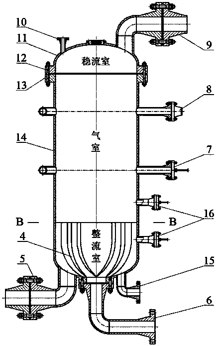
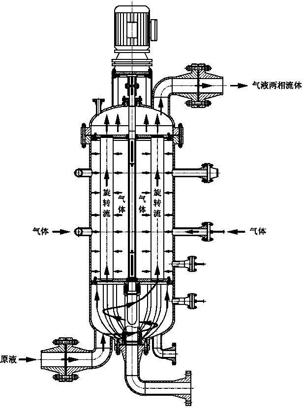
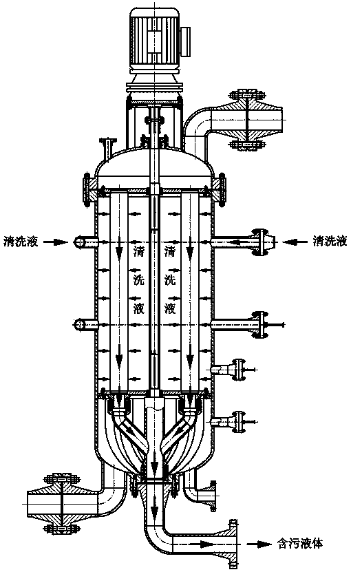
[0037] exist figure 1 and figure 2 Among them, the squirrel-cage self-flushing micro-bubble generator consists of self-flushing assembly 1, micro-bubble tank 2, squirrel-cage microporous membrane tube assembly 3, swirl blade 4, liquid inlet pipe 5, sewage pipe 6, air inlet pipe Sink 7, flushing manifold 8 and outlet pipe 9 are formed. When assembling, first connect the liquid inlet pipe 5, the sewage pipe 6 and their pipelines to the body of the microbubble tank 2 in sequence, and then put the flushing sleeve and the flushing pipe of the self-flushing assembly 1 into the rectifying chamber of the microbubble tank 2 And install the lower partition, then put the microporous membrane tube, transmission shaft and shaft sleeve into the air chamber of the microbubble tank 2 and install the upper partition, the uppermost end surface of the swirl vane 4 and the squirrel cage microporous membrane The positions of the microporous membrane tubes of the tube assembly 3 correspond one b...


PUM


Abstract

The invention provides a squirrel-cage type self-rinsing micro-bubble generator applied to air floatation treatment of oily sewage and industrial wastewater. A stock solution forms rotating flow on a rotating blade, and then enters a micro-porous membrane pipe to improve the utilization rate of gas; a ceramic-membrane membrane pipe ensures that generated micro-bubbles are fine and uniform in granularity and large in amount by adopting a squirrel-cage type arrangement and a honeycomb micro-fine pore structure and matching with an air inlet manifold; a control valve, a pressure safety valve and a differential pressure transmitter are arranged on the squirrel-cage type self-rinsing micro-bubble generator to ensure that the device is high in degree of automation; a motor drives a rinsing jacket and a rinsing pipe to continuously rotate to sequentially rinse the micro-porous membrane pipe until regeneration so as to finish the self-rinsing operation; the dirt of the micro-porous membrane pipe can be thoroughly cleaned by using the dual-cleaning of the combination of cleaning liquid rinsing operation and gas purging operation; a micro-bubble tank is designed with three closed chambers, namely a rectification chamber, a gas chamber and a steady-flow chamber; moreover, upper and lower division plates are connected with an annular plate by adopting screws, so that the micro-porous membrane pipe can be disassembled and replaced. The whole set of the device is compact in structure, easy in arrangement, operation and maintenance, and low in running cost.

Description

technical field [0001] The invention relates to a micro-bubble generator for air flotation treatment of oily sewage and industrial waste water. Background technique [0002] At present, pressurized dissolved air flotation and induced air flotation are widely used in municipal sewage and industrial wastewater treatment industries. [0003] Pressurized dissolved air flotation is divided into conventional pressurized dissolved air flotation and multiphase dissolved air pump air flotation system. The bubbles formed by conventional pressurized dissolved air flotation are small, but additional equipment such as gas pressurized conveying equipment, filler dissolved air tanks and degassers are required, which makes the system composition more complicated, the operation energy consumption is high, and the equipment occupies a relatively small area. Large; the multiphase dissolving air pump air flotation system completes the process of water pressurization, gas suction and dissolutio...

Claims


Application Information

Patent Timeline
IPC IPC(8): C02F1/24
Inventor 刘春花刘新福周超
Owner CHINA UNIV OF PETROLEUM (EAST CHINA)
Why Eureka
Try Eureka