
Automatic tool setting device and numerical control machining machine head

An automatic tool setting and machine head technology, applied in automatic control devices, metal processing machinery parts, feeding devices, etc., can solve the problems of dust pollution, automatic completion, and high environmental requirements, achieving low cost and improving processing efficiency. , the effect of simple mechanical structure

Inactive Publication Date: 2014-06-25
智慧工匠(北京)科技有限公司
View PDF7 Cites 1 Cited by
  • Summary
  • Abstract
  • Description
  • Claims
  • Application Information

AI Technical Summary

Problems solved by technology

[0003] At present, there are two traditional tool setting methods, one is completely manual tool setting, that is, the tool setting is realized manually with the help of paper or a tool setting block, and specifically, the tip of the CNC tool is pressed against the paper or the tool setting block The advantage of this method of tool setting is that it is simple, but the disadvantage is that it must be done manually and cannot be done automatically; the other is automatic laser tool setting, that is, the position of the CNC tool is corrected by measuring the distance with the laser. The advantage of the knife method is that it realizes automation, and has the advantages of fast speed and good accuracy, but the disadvantage is that it is expensive, has high environmental requirements, and cannot have dust pollution.
[0004] It can be seen from the above that although the traditional tool setting method can play a role in tool setting, there are still many deficiencies in the traditional tool setting method. And the tool setting device that has low requirements on the environment and can realize automatic measurement has become a problem that the industry needs to solve urgently.

Method used


Image

  • Automatic tool setting device and numerical control machining machine head
  • Automatic tool setting device and numerical control machining machine head

Examples


Embodiment Construction

[0018] The following will clearly and completely describe the technical solutions in the embodiments of the present invention with reference to the accompanying drawings in the embodiments of the present invention. Obviously, the described embodiments are only some, not all, embodiments of the present invention. All other embodiments obtained by persons of ordinary skill in the art based on the embodiments of the present invention belong to the protection scope of the present invention.

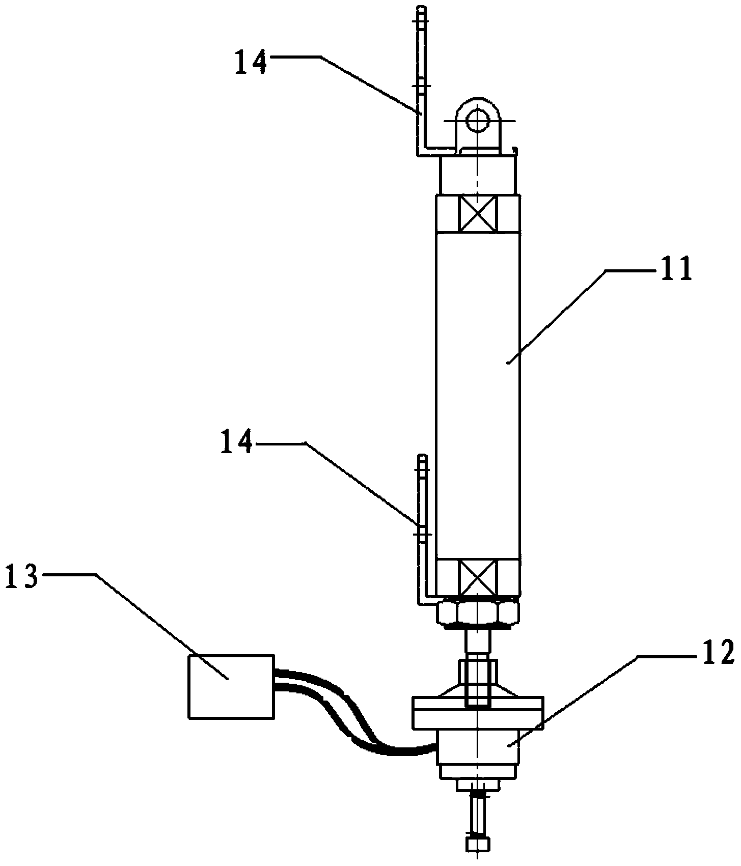
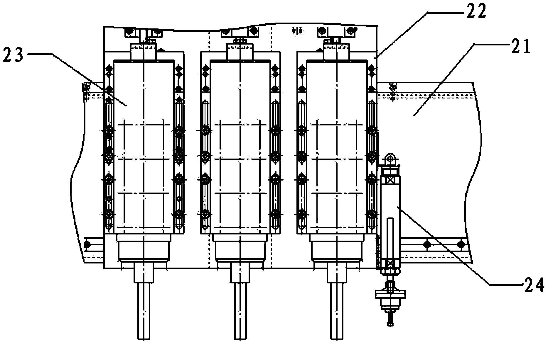
[0019] According to an embodiment of the present invention, an automatic tool setting device is provided. Such as figure 1 As shown, the automatic tool setting device according to the embodiment of the present invention includes a telescopic device 11, a trigger sensing device 12 and a tool controller 13, wherein the trigger sensing device 12 is arranged on the telescopic device 11, and acts on the telescopic device 11 The tool controller 13 is connected with the trigger sensing device 12, a...


PUM


Abstract

The invention discloses an automatic tool setting device which comprises a retractor device, a triggering sensing device and a tool controller. The triggering sensing device is arranged on the retractor device and moves in the stretching direction of the retractor device under the acting force of the retractor device; the tool controller is connected with the triggering sensing device and collects data fed back by the triggering sensing device to modify the position of a numerical control tool according to the data. By means of the automatic tool setting device, the triggering sensing device is in contact with the surfaces of machined materials by controlling the retractor device to determine the distance between the triggering sensing device and the surfaces of the machined materials, then determined distance parameters are fed back to the tool controller to enable the tool controller to conduct parameter modification on the numerical control tool according to the distance parameters, positional deviations of the numerical control tool are modified, the automatic tool setting function of the numerical control tool is further achieved, the distance between the tool and the machined materials is accordingly and effectively guaranteed, and the machining efficiency is improved.

Description

technical field [0001] The invention relates to the technical field of numerical control machine tool control, in particular to an automatic tool setting device and a numerical control machining head. Background technique [0002] In the field of CNC machine tools, when processing materials, whenever the processing materials are fixed on the processing table, the surface position of the processing materials must be known, so that the CNC tools can be processed effectively. In this context, there is The step of tool setting for the CNC tool is shown, that is, the position of the CNC tool is corrected. [0003] At present, there are two traditional tool setting methods, one is completely manual tool setting, that is, the tool setting is realized manually with the help of paper or a tool setting block, and specifically, the tip of the CNC tool is pressed against the paper or the tool setting block The advantage of this method of tool setting is that it is simple, but the disad...

Claims


Application Information

Patent Timeline
IPC IPC(8): B23Q15/22
CPCB23Q15/22B23Q17/20B23Q17/225
Inventor 高树公
Owner 智慧工匠(北京)科技有限公司
Learn More