
High frequency transformer rectification integrated device

A technology of high-frequency voltage transformation and components, which is applied in the direction of output power conversion device, AC power input conversion to DC power output, electrical components, etc., which can solve the problem of power supply stability and reliability reduction, large resistance loss and heat generation at the connection, To solve the problem of large cross-sectional area of ​​connecting copper bars, etc., to achieve the effect of improving power supply reliability, improving reliability, and reducing electromagnetic interference

Active Publication Date: 2016-09-21
SICHUAN INJET ELECTRIC CO LTD
View PDF7 Cites 0 Cited by
  • Summary
  • Abstract
  • Description
  • Claims
  • Application Information

AI Technical Summary

Problems solved by technology

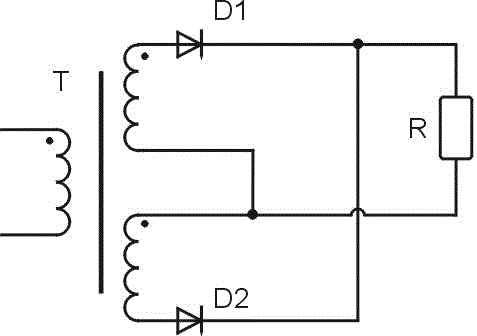
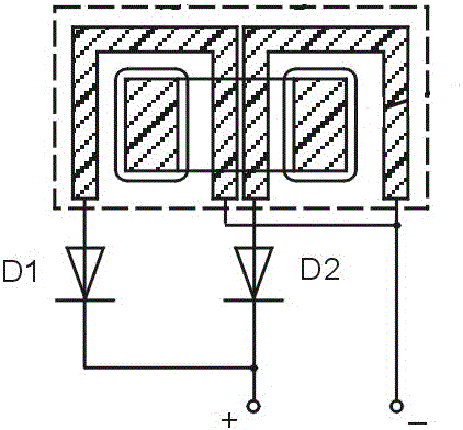
[0003] At present, the high-frequency transformer and the rectifier diode in the high-frequency inverter DC power supply are relatively independent (the circuit diagram and structure diagram are as follows: figure 1 , figure 2 ), usually the shape of the secondary coil is a cube or a cuboid structure, and the four electrodes of the secondary output of the high-frequency transformer are all located at the bottom of the transformer. The other two electrodes of the opposite end of the secondary are connected and output as the negative pole of the power supply. Due to the large output current and the large cross-sectional area of ​​the connecting copper bar, this type of connection structure has the following disadvantages: 1. The magnetic flux leakage at the bottom of the transformer is large, and high voltage will be generated at the bottom of the transformer. Frequency induction heating effect; 2. High-frequency magnetic flux leakage causes electromagnetic interference to circuits near the bottom, reducing power supply stability and reliability; 3. Leakage inductance generated by transformer magnetic flux leakage causes IGBT inverter switching at the front end of the transformer. Excessive peak voltage, which will pose a threat to the IGBT device; 4. Due to the small connection cross-section of the output electrode at the bottom of the transformer, the output current is large, and the existing structure is connected by screws, resulting in large resistance loss and heat generation at the connection Seriously, the reliability of the power supply is reduced; 5. The bottom structure leads to 4 electrodes, 2 of which are short-circuited and output as the negative output of the power supply, and the other 2 electrodes are respectively connected to the rectifier diode as the positive output. The number of electrodes is large and the connection is complicated. Diodes and Transformers are usually connected by copper bars, which leads to disadvantages such as large volume, complicated assembly, difficult maintenance, and reduced reliability of the inverter.

Method used


Image

  • High frequency transformer rectification integrated device
  • High frequency transformer rectification integrated device
  • High frequency transformer rectification integrated device

Examples


Embodiment Construction

[0027] Below in conjunction with accompanying drawing, the present invention is described in detail.

[0028] In order to make the object, technical solution and advantages of the present invention clearer, the present invention will be further described in detail below in conjunction with the accompanying drawings and embodiments. It should be understood that the specific embodiments described here are only used to explain the present invention, not to limit the present invention.

[0029] Such as Figure 5 and Figure 6 As shown, the high-frequency transformer-rectification integrated device of the present invention includes an annular magnetic core 1, a primary coil 2, a connecting core 3, a first secondary coil assembly 4, and a second secondary coil assembly 5. The connecting core 3 includes two half cylinders twisted 180 degrees, the two half cylinders are twisted and insulated from each other, the first secondary coil assembly 4 includes a first upper shell 41, a firs...


PUM


Abstract

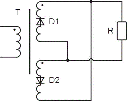
The invention discloses a high-frequency voltage transformation and rectification integrated device. According to the device, a rectifier diode is in serial connection with a secondary coil of a high-frequency transformer, the mode that all devices are independent and are connected through copper bars or wires in the prior art is changed, connection without cables or the copper bars of the rectifier diode and the high-frequency transformer is achieved due to ingenious design, and accordingly the high-frequency transformer and the rectifier diode are integrated organically and compactly; a diode is directly connected with an upper shell and a lower shell of a secondary coil assembly and can be cooled through the upper shell and the lower shell, and therefore heat dissipation design of the diode is avoided; meanwhile, by means of the device, four output electrodes at the bottom of the transformer of the original scheme are reduced to two output electrodes, and accordingly the structure of the bottom of the transformer is simplified. Compared with the prior art, the size of the integrated device is greatly reduced.

Description

technical field [0001] The invention relates to a voltage transformation and rectification device, in particular to a high-frequency voltage transformation and rectification integrated device. Background technique [0002] The high-frequency transformer and rectifier circuit of the high-frequency inverter DC power supply are one of the important factors determining the performance of the power supply. The traditional high-frequency inverter rectifier circuit adopts a structure in which each part of the device is independent of each other. The IGBT component, the high-frequency transformer, and the output rectifier Circuits, drive circuits, etc. are independent of each other. Devices are connected by wires or copper bars. The connection between high-current devices, due to the large size of wires or copper bars, makes the circuit complex, large loss, and easy to generate electromagnetic interference to surrounding circuits. , Reducing the use of wires or copper bars can reduc...

Claims


Application Information

Patent Timeline
Patent Type & Authority Patents(China)
IPC IPC(8): H02M7/00
Inventor 王军刘少德
Owner SICHUAN INJET ELECTRIC CO LTD
Learn More