
Microscopic video image objective lens compensation method

A technology of objective lens compensation and video image, applied in the direction of microscope, optics, instrument, etc., to achieve the effect of improving the overall clarity and improving the uniformity of illumination

Active Publication Date: 2014-06-11
NINGBO SUNNY INSTR
View PDF5 Cites 4 Cited by
  • Summary
  • Abstract
  • Description
  • Claims
  • Application Information

AI Technical Summary

Problems solved by technology

[0005] The present invention provides a microscopic video image objective lens compensation method, which mainly solves the above-mentioned two problems by using a software algorithm to compensate different objective lenses, so that the overall illumination uniformity of the microscopic video image, the overall Image clarity is greatly improved

Method used


Image

  • Microscopic video image objective lens compensation method
  • Microscopic video image objective lens compensation method

Examples


Embodiment Construction

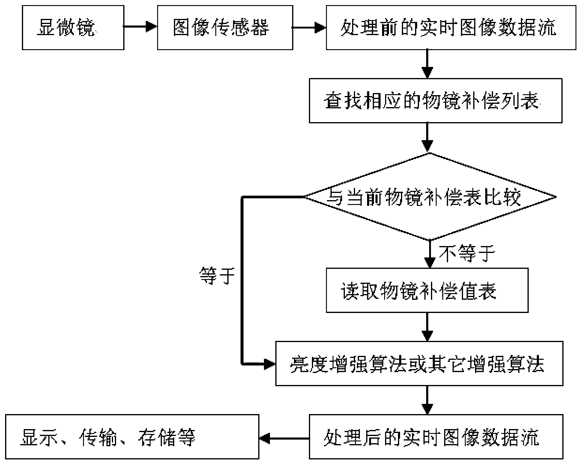
[0019] The realization of algorithm of the present invention is as figure 1 Shown:

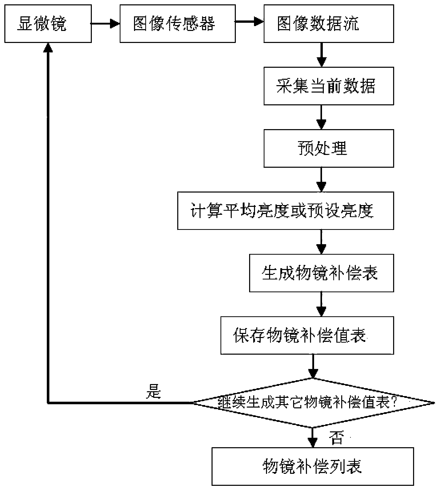
[0020] The image sensor is connected with the microscope through an optical adapter, and the collected microscopic image data stream is output to the processing chip. The processing chip searches for the corresponding objective lens compensation table in the pre-calculated and set objective lens compensation list according to the current microscope model, objective lens multiple, sensor chip type and image resolution. If the found compensation table is different from the current compensation table, read The corresponding objective lens compensation value table is obtained, and the compensation value of each pixel of the microscopic image is stored in the objective lens compensation value table. If the found compensation table is the same as the current compensation table, skip reading the objective lens compensation value table.

[0021] Wherein, the current compensation table is a compensat...


PUM


Abstract

The invention provides a microscopic video image objective lens compensation method. An image sensor is connected with a microscope through an optical adapter. The image sensor outputs collected microscopic image data flow to a processor. The processor reads a preset objective lens compensation value table to compensate each pixel point in the image data flow. Follow-up microscopic video image operations can be carried out on the processed real-time image data flow. Through the microscopic video image objective lens compensation method, the illumination uniformity of microscopic video images can be greatly improved, and the integral sharpness of the images can be improved.

Description

technical field [0001] The invention relates to an observation method of an optical digital microscope, which is applicable to all optical digital microscopes, and in particular relates to a microscopic video image objective lens compensation method. Background technique [0002] At present, when using an optical digital microscope for observation, because the image sensor is much more sensitive to the uniformity of illumination than the human eye, the human eye perceives an image with uniform illumination through the microscope eyepiece, but there will be a microscopic video image when observed through the image sensor The problem of light in the middle and dark edges. [0003] At the same time, due to the flatness of the objective lens, the microscopic video image still has the problem that the middle is clear and the edge is not clear enough, which affects the overall clarity of the image. [0004] The traditional image algorithm solution is to use an algorithm to increa...

Claims


Application Information

Patent Timeline
Patent Type & Authority Applications(China)
IPC IPC(8): G02B21/36
Inventor 杨鹏
Owner NINGBO SUNNY INSTR
Learn More