
A semiconductor device with an improved packaging structure and its manufacturing method

A packaging structure, semiconductor technology, applied in the direction of semiconductor/solid-state device manufacturing, semiconductor devices, semiconductor/solid-state device components, etc., can solve problems such as affecting the on-resistance of devices, reduce parasitic inductance, increase contact area, and fusing current. increased effect

Active Publication Date: 2016-06-15
无锡电基集成科技有限公司
View PDF5 Cites 2 Cited by
  • Summary
  • Abstract
  • Description
  • Claims
  • Application Information

AI Technical Summary

Problems solved by technology

The gate and emitter on the first main surface of a traditional IGBT chip and the collector on the second main surface; the maximum current of the emitter level will be limited by the number of metal leads bonded to the surface of the corresponding third pin top bonding area and wire size limitations, and affect the device on-resistance

Method used


Image

  • A semiconductor device with an improved packaging structure and its manufacturing method
  • A semiconductor device with an improved packaging structure and its manufacturing method
  • A semiconductor device with an improved packaging structure and its manufacturing method

Examples


Embodiment 1

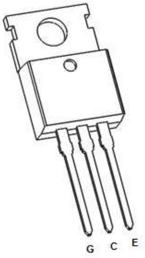
[0064] Such as image 3 As shown, on the three-dimensional perspective view of the semiconductor device, it includes a MOSFET chip, a TO-220 lead frame and a TO-220 packaging resin. The MOSFET chip has two corresponding main surfaces, namely a first main surface and a second main surface, wherein the first main surface has a gate and a source of the MOSFET chip, and the source area is much larger than the gate area, There is a drain electrode of a MOSFET chip on the second main surface; the TO-220 lead frame includes a frame body area located at the top of the lead frame, a carrier base island area at the middle of the lead frame, and a pin area at the bottom of the lead frame, three areas connected to each other; the second main surface of the MOSFET chip is adhesively mounted on the base island area of ​​the carrier; the pin area includes a first pin, a second pin and a third pin, and the second pin The pin is located in the middle of the first pin and the third pin; the to...

Embodiment 2

[0066] Such as Figure 4 As shown, on the three-dimensional perspective view of the semiconductor device, it includes a MOSFET chip, a TO-263 lead frame and a TO-263 packaging resin. The MOSFET chip has two corresponding main surfaces, namely a first main surface and a second main surface, wherein the first main surface has a gate and a source of the MOSFET chip, and the source area is much larger than the gate area, There is a drain electrode of a MOSFET chip on the second main surface; the TO-263 lead frame includes a frame body area located at the top of the lead frame, a carrier base island area at the middle of the lead frame, and a pin area at the bottom of the lead frame, three areas connected to each other; the second main surface of the MOSFET chip is adhesively mounted on the base island area of ​​the carrier; the pin area includes a first pin, a second pin and a third pin, and the second pin The pin is located in the middle of the first pin and the third pin; the t...


PUM


Abstract

The invention discloses a semiconductor device with an improved packaging structure and a manufacturing method thereof. The semiconductor device includes a semiconductor chip, a lead frame and a packaging resin. The semiconductor chip is located in the base island area of ​​the lead frame, and the lead frame includes a lead area, wherein the upper end of the second lead area is connected with a second bonding area. The semiconductor chip is electrically connected with the second bonding area through metal wires. The area of ​​the second bonding area is larger than that of the prior art, so as to ensure that the maximum fusing current limited by the metal leads can be effectively increased when the chip is packaged, and the on-resistance of the device is reduced, thereby maximizing the actual use of the chip. current capability. The invention is applicable to MOSFET devices and IGBT devices.

Description

technical field [0001] The invention relates to a packaged semiconductor device and a manufacturing method thereof, in particular to a power MOSFET device or an IGBT device with an improved packaging structure and a manufacturing method thereof, belonging to the technical field of semiconductor devices. Background technique [0002] Semiconductor devices can be finally used on PCB circuit boards, usually through two parts of the process of chip manufacturing and chip packaging. Therefore, the characteristics of the chip itself and the pros and cons of packaging technology directly determine the final performance of a device product. With the continuous improvement of the integration and fineness of chip processing technology, the performance of the chip itself has been greatly improved. In many cases, the packaging technology has become the bottleneck that limits the actual performance of the product. This is especially reflected in some high-power, High current semiconducto...

Claims


Application Information

Patent Timeline
Patent Type & Authority Patents(China)
IPC IPC(8): H01L23/495H01L23/31H01L21/60H01L21/56
CPCH01L24/97H01L2224/0603H01L2224/32245H01L2224/48247H01L2224/4903H01L2224/49111H01L2224/49175H01L2224/73265H01L2224/92247H01L2224/97H01L2924/13091H01L2224/48472H01L2924/1306H01L2924/13055H01L2924/1305H01L2924/181H01L2924/00H01L2924/00012
Inventor 朱袁正叶鹏朱久桃
Owner 无锡电基集成科技有限公司
Learn More