
Pressure-reduction, anti-explosion and dust-removal device for aerodynamic reservoir reform of coal-bed gas well

An aerodynamic and reservoir transformation technology, applied in dust prevention, safety devices, fire prevention, etc., can solve problems such as damage to facilities around the construction site, gas deflagration, loud noise, etc., to eliminate unsafe factors, prevent gas deflagration, well-designed effects

Active Publication Date: 2014-05-28
河南省资源环境调查二院
View PDF7 Cites 2 Cited by
  • Summary
  • Abstract
  • Description
  • Claims
  • Application Information

AI Technical Summary

Problems solved by technology

In the gas injection stage, the air compressor compresses the air into the coalbed methane well. When the pressure reaches above 10MPa, it enters the pressure release stage after closing the pressure. (Rock) powder or particles, gas gas is directly thrown into the air, and the coal (rock) powder or particles carried are easy to collide with objects and generate sparks, causing gas deflagration, damaging the facilities around the construction site and threatening personal safety
At the same time, when the high-pressure gas is released, the noise is huge, and the coal particles and dust seriously pollute the environment and affect the lives of nearby residents.
So far, there is no relevant supporting device and technology to solve the practical problems existing in the prior art

Method used


Image

  • Pressure-reduction, anti-explosion and dust-removal device for aerodynamic reservoir reform of coal-bed gas well
  • Pressure-reduction, anti-explosion and dust-removal device for aerodynamic reservoir reform of coal-bed gas well
  • Pressure-reduction, anti-explosion and dust-removal device for aerodynamic reservoir reform of coal-bed gas well

Examples


Embodiment Construction

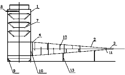
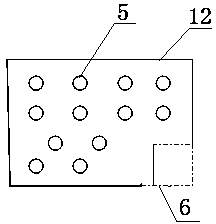
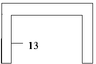
[0011] Below in conjunction with accompanying drawing, provide embodiment of the present invention as follows: figure 1 , figure 2 , image 3 , Figure 4 As shown, a kind of coalbed methane well aerodynamic reservoir transformation decompression and explosion-proof dust removal device according to the present invention is mainly composed of dust collector 1, diffuser pipe 2, and air intake pipe 3; Welded thick steel plate. The dust collector 1 has an overall height of 7000mm and a diameter of 2400mm. It is divided into upper, middle and lower sections, and each section is connected together with bolts. The height dimension of the lower section of the dust collector 1 is 2600mm, and one side of the lower section is provided with an air inlet 10, and the air inlet 10 and the diffuser pipe 2 are connected by bolts through the diffuser pipe connection port 4. The bottom of the lower section of the dust collector 1 is welded with a first-stage vane-type swirl plate tray 7, and...


PUM


Abstract

The invention provides a pressure-reduction, anti-explosion and dust-removal device for aerodynamic reservoir reform of a coal-bed gas well, and is applicable to the technical field of gas power operation of the coal-bed gas well. The pressure-reduction, anti-explosion and dust-removal device mainly comprises a dust remover (1), a diffusion tube (2) and a gas feeding tube (3). During technical construction of a gas power reform coal storage reservoir, high-flow-speed gas is not directly released in air in a pressure releasing stage, is guided by the gas feeding tube (1) to enter the diffusion tube (2), and is subjected to eight pressure reduction effects under the action of eight wind shields (12) in the diffusion tube (2). Gas flows to the dust remover (1) through auxiliary round ventilating holes (5) in the wind shields (12), and coal (rock) powders or particles in the gas are stopped by the wind shields (12), drop, are blown by the gas, enter the dust remover through a coal passing hole (6) and then are removed. A four-stage blade type vortex plate tower tray (7) is arranged in the dust remover (1), the gas is forced to spirally rise by using the four-stage blade type vortex plate tower tray (7), and liquid flow is formed by water flow injected through a water injection tube, is distributed on blades of the vortex plate tower tray (7), is thrown to a wall of a tower by centrifugal force, and then flows in a water draining hole (9).

Description

technical field [0001] The invention belongs to the technical field of coalbed gas well gas power operation, and mainly relates to a decompression, explosion-proof and dust removal device for coalbed gas well aerodynamic reservoir transformation. Background technique [0002] In coalbed methane wells, the transformation of coal reservoirs by gas power is an effective technical means to improve the productivity of coalbed methane wells. The principle is: inject high-pressure air into the coalbed methane well, and the high-pressure air will expand the cracks in the coal reservoir, and then release the pressure. The purpose of dredging and expanding reservoir fractures is to generate new induced fractures, thereby enhancing the permeability of coal reservoirs and improving the gas production capacity of coal reservoirs. [0003] Generally speaking, the process of coal reservoir transformation by gas power is divided into seven stages, including: test injection stage, initial i...

Claims


Application Information

Patent Timeline
Patent Type & Authority Applications(China)
IPC IPC(8): E21F5/00
Inventor 张建奇雷华友罗锐冯跃封任贵阳高永斌朱玉新房雪峰
Owner 河南省资源环境调查二院
Learn More