Eureka AIR delivers breakthrough ideas for toughest innovation challenges, trusted by R&D personnel around the world.

Traction runway for automobile safety crash laboratory and layered construction method of the traction runway

A technology of automobile safety and layered construction, applied in the field of automobile crash test, can solve the problems of inability to carry out crash test, inaccurate crash test, affecting the flatness of the ground, etc., to achieve the effects of vibration compaction, risk reduction, and ease of heat dissipation

Active Publication Date: 2014-05-28
CHINA AUTOMOTIVE TECH & RES CENT
View PDF5 Cites 6 Cited by
  • Summary
  • Abstract
  • Description
  • Claims
  • Application Information

AI Technical Summary

Problems solved by technology

[0003] Referring to the general indoor ground construction technology, combined with the requirements of the embedded traction track, if the general one-time concrete pouring molding process is adopted, the problems of honeycomb, pockmarks, and dog holes caused by uneven vibration during the concrete molding process, and the hardening process Self-shrinkage problem, these uncontrollable factors will directly affect the final flatness of the ground, and this effect is irreparable, which will eventually lead to inaccurate crash tests or even failure to conduct crash tests

Method used


Image

  • Traction runway for automobile safety crash laboratory and layered construction method of the traction runway
  • Traction runway for automobile safety crash laboratory and layered construction method of the traction runway
  • Traction runway for automobile safety crash laboratory and layered construction method of the traction runway

Examples


Embodiment Construction

[0029] Specific embodiments of the present invention are described below in conjunction with accompanying drawing:

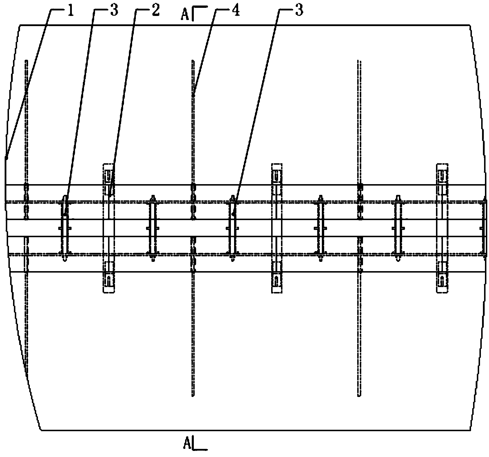
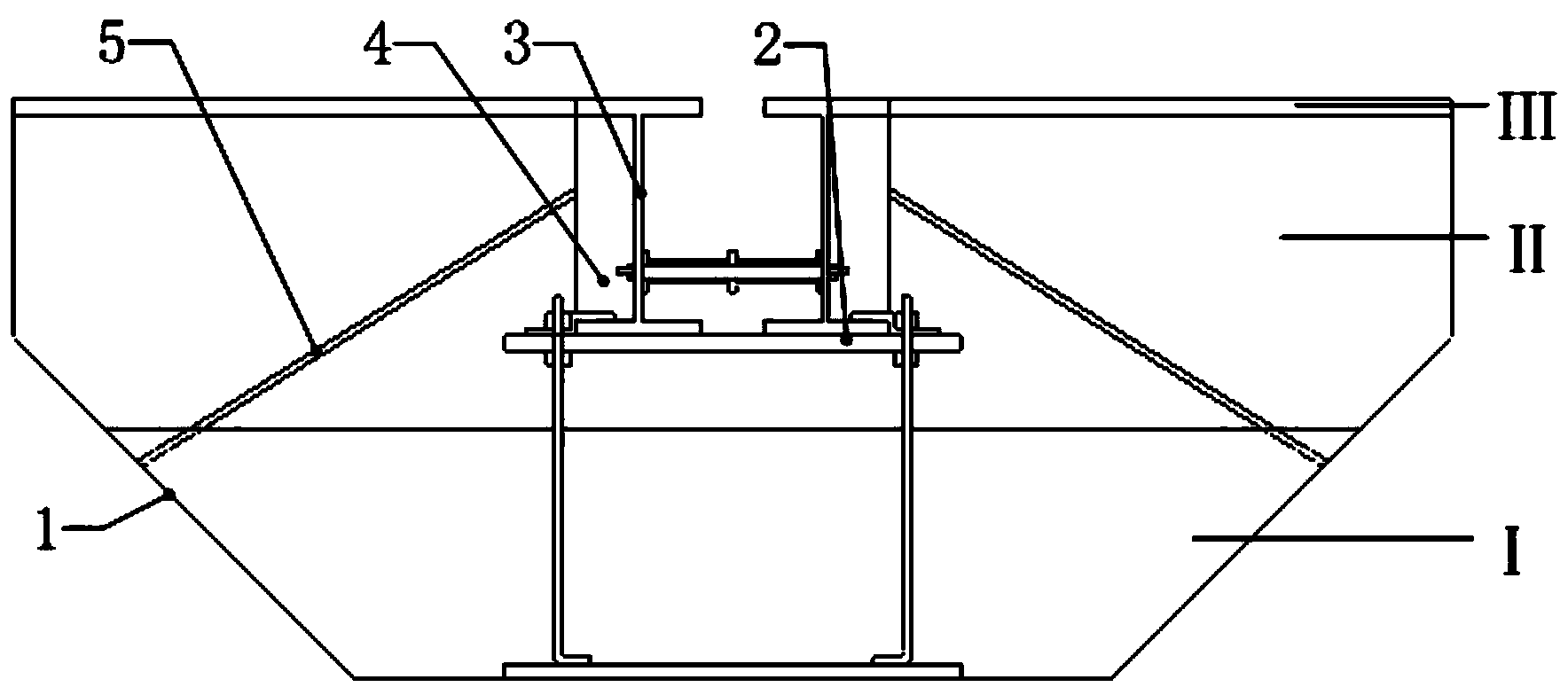
[0030] A kind of traction runway for automobile safety collision test room, its length can be set according to needs, the present embodiment is 100-200m, it comprises foundation groove 1, is installed with several groups of supporting devices interconnected in foundation groove 1, in the supporting device A concrete layer is cast between the foundation tank 1 and an asphalt layer III is laid on the upper surface of the concrete layer;

[0031] in:

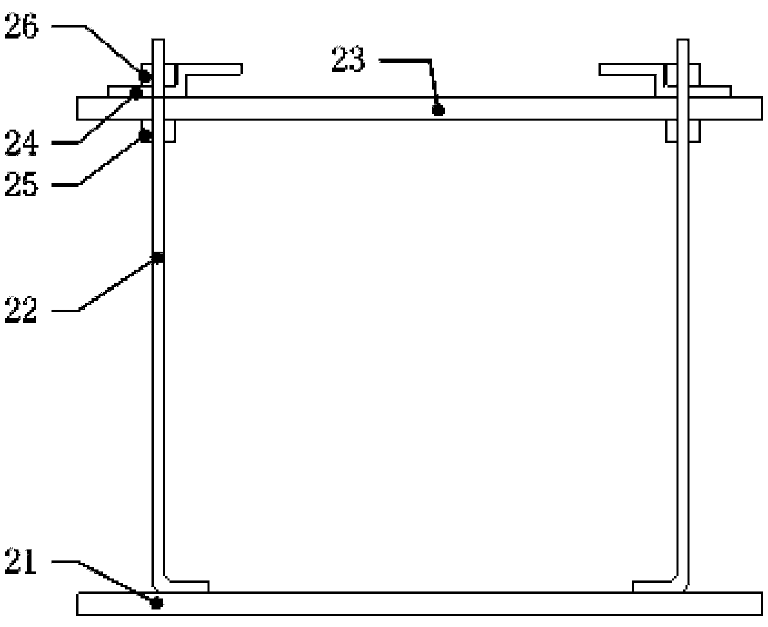
[0032] The support device includes a height adjustment bracket 2 installed on the bottom surface of the base groove 1, an H steel support mechanism 3 assembled on the top of the height adjustment bracket 2 and clamped on it, and a number of H steel reinforcement bars 4 are welded on both sides of the H steel support mechanism 3 , the H-steel reinforcing bar 4 is welded with a restraining steel bar 5, and the other e...


PUM


Abstract

The invention provides a traction runway for an automobile safety crash laboratory. The traction runway comprises a foundation trench, a plurality of groups of supporting devices, a concrete layer and an asphalt layer, wherein the plurality of groups of supporting devices are arranged in the foundation trench and are connected with each other; the concrete layer is poured between the supporting devices and the foundation trench; the asphalt layer is paved on the upper surface of the concrete layer; each supporting device comprises a height adjusting bracket, an H-steel supporting mechanism, a plurality of H-steel reinforcing ribs and restrained steel bars, wherein the height adjusting bracket is arranged on the bottom of the foundation trench, the H-steel supporting mechanism is assembled above the height adjusting bracket, the plurality of H-steel reinforcing ribs are fixedly connected to two sides of the H-steel supporting mechanism, one ends of the restrained steel bars are connected to the H-steel reinforcing ribs, and the other end of the restrained steel bars are obliquely inserted into the restrained steel bars located in the foundation trench; the concrete layer is divided into a bottom concrete layer and a middle concrete layer, wherein the bottom concrete layer is lower than the height adjusting bracket, the middle concrete layer is poured on the bottom concrete layer, and the poured concrete layer is lower than the upper surface of the H-steel supporting mechanism. The traction runway has the beneficial effects that the flatness of the traction runway can be adjusted step by step, and asphalt is paved on the topmost layer, so that a pavement can be repaired at any time, and furthermore, the accuracy of an automobile crash test is ensured.

Description

technical field [0001] The invention relates to the technical field of automobile collision tests, in particular to a traction track for an automobile safety collision test room and a layered construction method thereof. Background technique [0002] Automobile crash test is an important means to study automobile safety. It can reproduce the collision form of vehicles under most traffic conditions, and has become an important way to test and evaluate the research of automobile passive safety. In order to reproduce the vehicle collision form in the test room, the vehicle under test needs to be accelerated from static to the specified collision speed. For the purpose of test safety, the vehicle collision test must not rely on vehicle power to accelerate the vehicle, but to use traction to make the vehicle reach the specified speed. For this reason, the design of the collision test traction runway should consider the embedded traction during road construction. Rails, used to c...

Claims


Application Information

Patent Timeline
Patent Type & Authority Applications(China)
IPC IPC(8): E01C9/00G01M17/007
Inventor 陈弘刘海方哲孙制宇
Owner CHINA AUTOMOTIVE TECH & RES CENT
Why Eureka
Eureka Blog
Learn More