
Coal field fire area wireless sensor monitoring node

A wireless sensor and monitoring node technology, applied in instruments, measurement devices, signal transmission systems, etc., can solve problems such as high power consumption, limited node application, and unspecific applications, achieve stable performance, prevent node crashes, and prevent running fly effect

Inactive Publication Date: 2014-05-21
JIANGSU UNIV
View PDF6 Cites 7 Cited by
  • Summary
  • Abstract
  • Description
  • Claims
  • Application Information

AI Technical Summary

Problems solved by technology

There are problems in the direct application of the existing technology in the monitoring of coalfield fire areas: (1) The finished wireless sensor nodes [1-2] are mostly development platforms with rich interfaces and unspecific applications; there are many peripheral circuits and relatively large power consumption. It needs to be trimmed for specific use
(2) Literature [3] describes the connection relationship between the modules of the node, but does not involve specific peripheral support circuits
The node [4] developed for large-scale transmitters describes the peripheral circuit, which is oriented to special needs and has specific functions. It is not applicable to coalfield fire area monitoring
(3) The basic application of commonly used chips [5-6] has power supply, external crystal oscillator and antenna matching circuit, which can perform wireless transmission and reception normally, but does not have functions such as signal acquisition, which limits the application of nodes in coal field fire monitoring. Additional peripheral circuits need to be designed

Method used


Image

  • Coal field fire area wireless sensor monitoring node
  • Coal field fire area wireless sensor monitoring node

Examples


Embodiment Construction

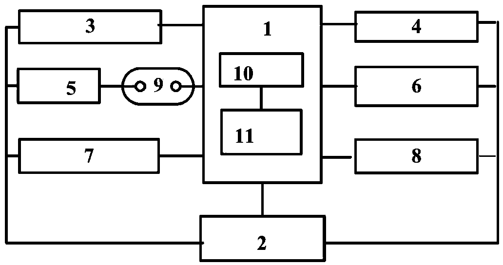
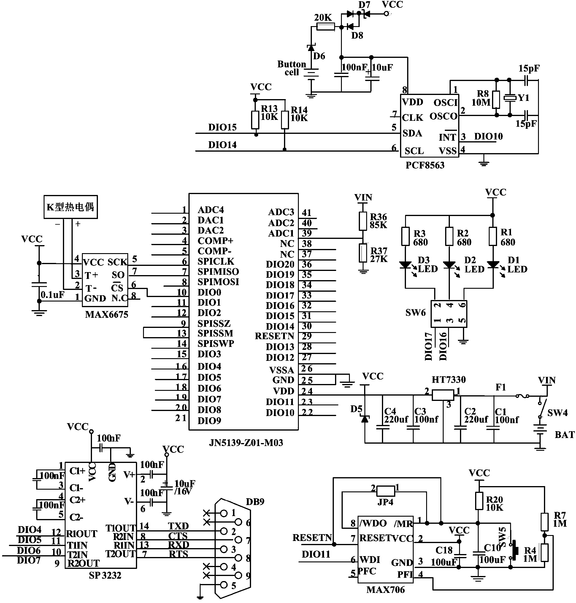
[0034] In order to further explain the purpose, technical solutions and beneficial effects of the present invention, taking the JN5139-Z01-M03 wireless microprocessor as the node core chip as an example, it will be described in detail from two aspects of node structure design and node circuit principle.

[0035] 1. The wireless sensor monitoring node structure of the present invention is as follows: figure 1 shown.

[0036] 1) The wireless microprocessor 1 selects JN5139-Z01-M03 produced by Jennic Company, which integrates the wireless radio frequency module 10 and the processor 11 . JN51XX wireless sensor series chips have an operating voltage of 2.7-3.6V, a receiver sensitivity of -96.5dBm, a transmit power of +2.5dBm, a transmit current 2 C, DIO, etc.

[0037] 2) The power supply circuit 2 is connected with the wireless microprocessor 1, external clock 3, watchdog 4, LED lamp group 5, RS232 serial port 6, voltage measurement circuit 7 and high temperature acquisition circu...


PUM


Abstract

The invention discloses a coal field fire area wireless sensor monitoring node. The coal field fire area wireless sensor monitoring node comprises a wireless microprocessor, a power supply circuit, an external clock, a watchdog member, LED (light-emitting diode) lamp sets, an RS232 (recommend standard 232) serial port, a voltage measuring circuit and a high temperature acquisition circuit. The designed peripheral circuits correspond to monitoring requirements respectively, the functions are specific, and redundant components are omitted. The LED lamp sets are connected with a power supply and the wireless microprocessor through a jumper, the jumper is turned on during debugging, and the jumper is turned off during using, so that energy consumption can be reduced. All circuits and chips are integrated into a circuit board, components are firmly connected, and the working performance is stable. The coal field fire area wireless sensor monitoring node is applicable to coal field fire area monitoring to collect the temperature, ambient temperature and humidity, battery voltage of an underground coal seam in a fire area. The coal field fire area wireless sensor monitoring node has functions of synchronous dormant, watchdog, power protection, brownout detection and the like, and is low in power consumption and long in service life.

Description

technical field [0001] The invention belongs to the technical field of wireless sensors, and in particular relates to hardware circuits of wireless sensor nodes. Background technique [0002] Coalfields have caused huge losses due to spontaneous combustion. In order to monitor the disaster situation, the temperature of the coalfield fire area, especially the temperature of the fire area after treatment, has dropped to extinguishment, or the process of re-ignition of accumulated temperature is monitored. The wireless sensor network gathers the measurement data of the high-temperature sensors arranged in the fire area in a wireless manner and sends them to the monitoring center through the remote transmission system, so as to realize the measurement work that cannot be completed by manual and wired transmission methods. The Xinjiang fire area is far away from infrastructure, and manual replacement and maintenance are inconvenient. It is required that the wireless sensor networ...

Claims


Application Information

Patent Timeline
IPC IPC(8): G01D21/02G08C17/02
Inventor 曹清华闫述谭成龙朱娜
Owner JIANGSU UNIV
Learn More