Cage type electric mini-tiller and application thereof

A micro-tiller, electric technology, applied in the field of agricultural machinery, can solve the problems of high cost, difficulty in starting, high failure rate, and achieve the effects of light weight, low ground breaking power and small volume

Inactive Publication Date: 2014-05-21
东莞开拓机械制造有限公司 +1
View PDF5 Cites 3 Cited by
  • Summary
  • Abstract
  • Description
  • Claims
  • Application Information

AI Technical Summary

Problems solved by technology

However, due to reasons such as the noise and exhaust pollution of the micro tillage machine, its application in some occasions is limited, such as agricultural environments such as small family vegetable gardens, modern farms and greenhouses, especially modern pig farms. When manure is excreted in the pig house, a tiller is needed to crush the pig manure that is trampled on the floor. The exhaust gas and noise of the gasoline-powered micro-tiller will affect the normal growth of pigs
In addition, the maintenance of general micro tillage machines is complicated and costly, especially after the gasoline engine is aging, it is difficult to start and the failure rate is high

Method used


Image

  • Cage type electric mini-tiller and application thereof
  • Cage type electric mini-tiller and application thereof
  • Cage type electric mini-tiller and application thereof

Examples


Embodiment 1

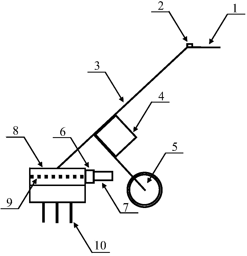
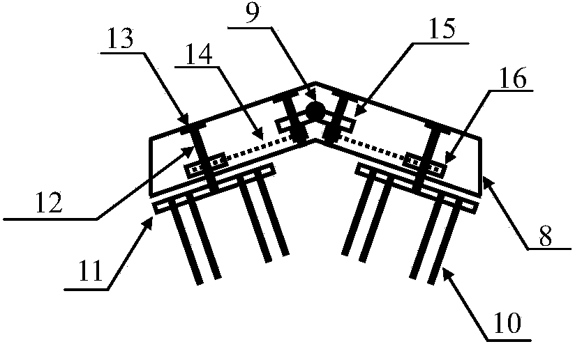
[0024] Such as figure 1 As shown, a cage-type electric tiller includes a frame 3, a machine head, a power mechanism, a transmission mechanism and an actuator; a control switch 2 is installed on the inside of the handle 1; one end of the frame 3 is fixedly connected with the handle 1, and the frame The other end of 3 is fixedly connected with shell 8, and the middle part of frame 3 is equipped with travel wheel 5, and power control box 4 is fixed on the junction of frame 3 and travel wheel 5 and plays tripod reinforcement effect, when non-cultivation operation walks, With the traveling wheel 5 as the fulcrum, the handle 1 is pressed down to raise the machine head to a certain height so that it can walk freely. Such as figure 2 As shown, the handpiece includes a shell 8, which is an inverted "V"-shaped shell with a cavity formed inside. Such as Figure 6 As shown, the power mechanism includes a motor 7, a reducer 6 and a lead screw 9, the motor 7 is fixed on the outer rear c...

Embodiment 2

[0027] The principle is the same as in Embodiment 1, and the storage battery inside the power supply control box 4 is a lithium-ion battery or a lead-acid storage battery, or is refitted into a wired power supply mode. Drive chain 14 can be changed into belt, and corresponding sprocket wheel also changes belt pulley into. The angle of the inverted "V"-shaped shell 8 can be adjusted according to the compactness and depth of the cultivation object. Generally, when the soil is loose or the cultivation depth is large, the angle of the "V" shape is smaller, and vice versa.


PUM


Abstract

The invention discloses a cage type electric mini-tiller. The cage type electric mini-tiller comprises a machine frame, a machine head, a power mechanism, a transmission mechanism and executing mechanisms. The executing mechanisms are symmetrically distributed at the two ends of the machine head. A tillage wheel axle is perpendicular to the upper surface of an outer shell, and the tillage wheel axle is fixed inside the outer shell through an upper end locating bearing of the tillage wheel axle and a lower end locating bearing of the tillage wheel axle. A tillage wheel axle chain wheel and a tillage wheel disk are coaxially connected, are fixed on the tillage wheel axle and can rotate freely. The tillage wheel axle chain wheel and a driving chain wheel are connected in a meshed mode through a transmission chain. The tillage wheel disk is placed outside the outer shell, and the tillage wheel disk is fixedly provided with a plurality of cylindrical tillage wheel teeth. The cage type electric mini-tiller has the advantages of being small in size, low in weight, low in noise, free of tail gas, suitable for tillage operations such as plowing and soil loosening in small land blocks and in a room, and the like.

Description

technical field [0001] The invention relates to the field of agricultural machinery, in particular to a cage-type electric tiller and its application. Background technique [0002] Mini-tillers are widely used and have a high market retention rate. At present, micro-tillers generally use gasoline or diesel engines as power, and have a large volume and weight, which is suitable for field operations. However, due to reasons such as the noise and exhaust pollution of the micro tillage machine, its application in some occasions is limited, such as agricultural environments such as small family vegetable gardens, modern farms and greenhouses, especially modern pig farms. When manure is excreted in a pig house, a tiller is needed to crush the pig manure that is trampled on the floor. The exhaust gas and noise of a gasoline engine-powered tiller will affect the normal growth of pigs. In addition, general micro tillage machines are complex and costly to maintain, especially after t...

Claims


Application Information

Patent Timeline
IPC IPC(8): A01B33/02A01B33/10
Inventor 孙永生闫国琦杨洲朱嘉琪陈志浩林孙鸿
Owner 东莞开拓机械制造有限公司
Why Eureka
Try Eureka