Available ways based on ultrasound interoperability technology ratio measurement methods for fluid flow rate
What is Al technical title?
Al technical title is built by PatSnap Al team. It summarizes the technical point description of the patent document.
A fluid velocity and measurement method technology, applied in fluid velocity measurement, velocity/acceleration/impact measurement, measurement device, etc. The effect of the adjustable turndown ratio
Inactive Publication Date: 2016-06-29
YANSHAN UNIV
View PDF3 Cites 0 Cited by
Summary
Abstract
Description
Claims
Application Information
AI Technical Summary
This helps you quickly interpret patents by identifying the three key elements:
Problems solved by technology
Method used
Benefits of technology
Problems solved by technology
[0013] The range of traditional measurement methods is limited by the relative error caused by the peak position, resulting in a decrease in the accuracy of the measurement results. Therefore, how to expand the measurement range of flow velocity under the premise of keeping the relative error caused by the peak position unchanged has always been a difficult problem
Method used
Image
Click on the blue label to locate the original text in one second.
Reading with bidirectional positioning of images and text.
Examples
Embodiment 1
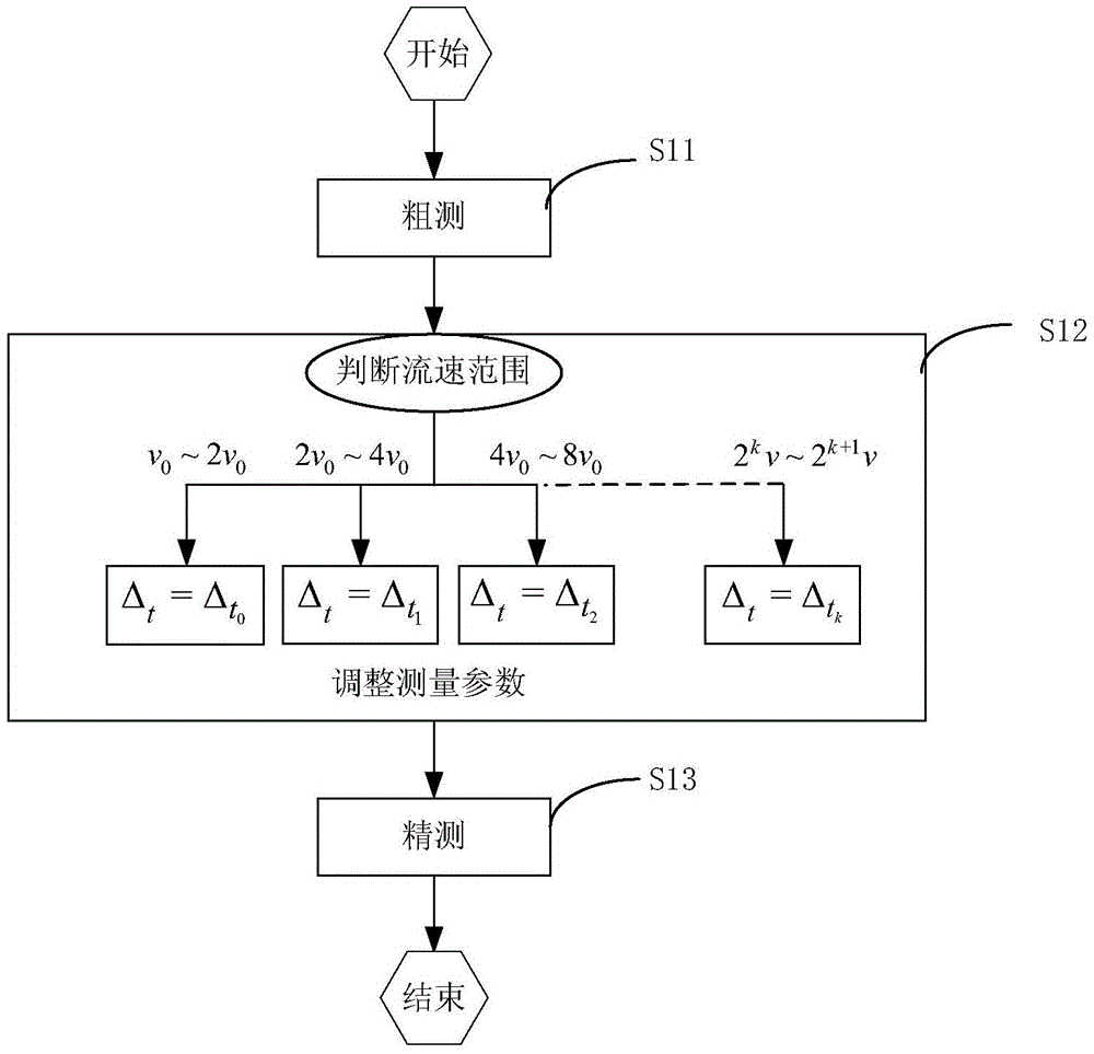
[0037] refer to figure 2 ,include:
[0038] Step S11) Use a lower pulse train frequency and a larger sampling time interval to roughly measure the current flow rate;
[0039] Step S12) Select the corresponding range range according to the rough measurement result and multiple preset measurement intervals to adjust the measurement parameters during precise measurement, including pulse train frequency and sampling time interval;
[0040] Step S13) Precise measurement to ensure that the measurement results meet the accuracy requirements;
[0041] In the above embodiment, it is assumed that the total number of sampling points N is 256, the upper limit of each preset measurement interval is 100, and the lower limit is 200, and the lag time meets the relevant detection requirements of random signals. Therefore, the ratio of the upper limit to the lower limit of each measurement interval is 2, then the relative error caused by the peak position is 0.5% to 1% in each interval.
[...
Embodiment 2
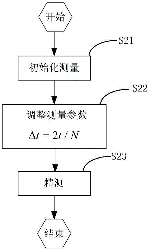
[0047] refer to image 3 ,include:
[0048] Step S21) Initialize the measurement, use a lower burst frequency and a larger sampling time interval, and roughly determine the lag time;
[0049] Step S22) Adjust measurement parameters according to the measured lag time, including burst frequency and sampling time interval;
[0050] Step S23) Precise measurement to ensure that the measurement results meet the accuracy requirements.
[0051] In this embodiment, in order to ensure a better correlation between the two signals and the accuracy of the correlation results, the number of lagging points n during fine measurement is around N / 2, so that the precise measurement results remain as Then the adjusted sampling time interval and burst time interval are Δ t =2t / N.
PUM
Abstract
The invention discloses a fluid flow velocity measurement method with an adjustable measuring range ratio based on an ultrasonic cross-correlation technology. Two pairs of upstream sensors 1 and downstream sensors 2 are respectively arranged in the diameter direction in the section, perpendicular to fluid, of the outer edge of a pipe wall, the sensors simultaneously transmit and receive ultrasonic pulse signals, flow velocity measurement with the adjustable measuring range ratio is achieved on the premise of guaranteeing measuring result precision, and based on the relation between a measuring range and sampling time intervals and setting on delay time, flow velocity measurement with the adjustable measuring range ratio comprises the steps of rough measurement, measurement parameter adjustment and fine measurement, wherein measurement parameters comprise pulse string time intervals and the sampling time intervals. The contradictory relation between accuracy and the measuring range ratio in a traditional measurement method is eliminated, it is guaranteed that relative errors caused by the determination of a peak position are kept consistent within the range of each measuring range, and therefore the accuracy of the measurement result is guaranteed. The method is simple in use, the measuring range selection step is eliminated for the initialization on the sensors, and self-adaptive measurement can be achieved.
Description
technical field [0001] The invention relates to a fluid flow velocity measurement technology, in particular to a flow velocity measurement method based on ultrasonic cross-correlation technology. Background technique [0002] Ultrasonic correlation method flow velocity measurement has been widely concerned because of its non-invasive, high accuracy, no need for sound velocity information, not affected by changes in the external environment such as temperature, and can measure single-phase flow and multi-phase flow. [0003] The cross-correlation velocity measurement is based on the coagulation flow pattern hypothesis. According to this hypothesis, the random noise of the fluid in a section upstream will reappear in a section downstream after a certain period of time. The time during which this fluid random noise passes upstream and downstream is called lag time. The sensor includes an upstream sensor and a downstream sensor, which are respectively installed on two sections ...
Claims
Application Information
Patent Timeline
Application Date:The date an application was filed.
Publication Date:The date a patent or application was officially published.
First Publication Date:The earliest publication date of a patent with the same application number.
Issue Date:Publication date of the patent grant document.
PCT Entry Date:The Entry date of PCT National Phase.
Estimated Expiry Date:The statutory expiry date of a patent right according to the Patent Law, and it is the longest term of protection that the patent right can achieve without the termination of the patent right due to other reasons(Term extension factor has been taken into account ).
Invalid Date:Actual expiry date is based on effective date or publication date of legal transaction data of invalid patent.