Piezoelectric electret film key

A piezoelectric electret and film technology, applied in the field of piezoelectric electret film keys, can solve the problems of increased process cost, low sensitivity, complex structure, etc., and achieve the effects of saving power consumption, small size, and strong flexibility

Active Publication Date: 2014-05-07
BEIGU NEW MATERIAL TECH SHANGHAI
View PDF9 Cites 5 Cited by
  • Summary
  • Abstract
  • Description
  • Claims
  • Application Information

AI Technical Summary

Problems solved by technology

However, the PVDF piezoelectric film used in the above patents has low sensitivity (piezoelectric charge coefficient d33 is about 25pC / N), and high cost has become the main reason for its limited application.
In addition, the above-mentioned patent adopts the method of separating the piezoelectric film from the FPC lead-out line, which not only has a complicated structure, but also increases the process cost

Method used


Image

  • Piezoelectric electret film key
  • Piezoelectric electret film key
  • Piezoelectric electret film key

Examples


Embodiment 1

[0033] Example 1: Combining figure 1 , the piezoelectric electret film button, including a piezoelectric electret film 1, an upper surface electrode 2 attached to the upper surface of the piezoelectric electret film 1, and a lower surface electrode attached to the lower surface of the piezoelectric electret film 1 3. The upper surface encapsulation layer 4 and the lower surface encapsulation layer 5 encapsulated in the outer layer of the upper surface electrode 2 and the lower surface electrode 3, the surface layer 6 located on the upper surface encapsulation layer, and the lower surface shield located below the lower surface encapsulation layer 5 Layer 7 and base layer 8.

[0034] The piezoelectric electret film 1 is an organic film containing a micro-hole structure, and permanent charges are stored inside the micro-hole structure.

[0035] The lower surface electrode 3, such as figure 2 As shown, it consists of three mutually independent conductive electrodes 31 , and eac...

Embodiment 2

[0041] Embodiment 2: another kind of embodiment of the present invention, overall lamellar structure is identical with embodiment 1, and difference is:

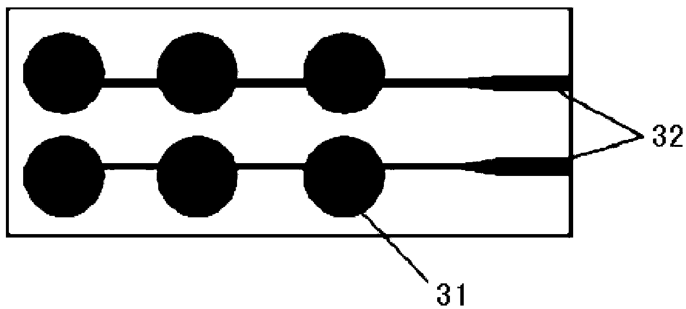
[0042] The lower surface electrode 3, such as image 3 As shown, it consists of two vertically arranged conductive electrode groups, and each conductive electrode group is composed of three horizontally arranged conductive electrodes 31 in series, and each conductive electrode group is led out by a wire 32 respectively.

[0043] The upper surface electrode 2, such as Figure 5 As shown, it consists of three sets of conductive electrode groups arranged horizontally, and each conductive electrode group is formed by two vertically arranged conductive electrodes 21 in series, and each conductive electrode group is led out by a wire 22 respectively.

Embodiment 3

[0044] Embodiment 3: Another embodiment of the present invention is based on Embodiment 1 or Embodiment 2, modifying the structure of the upper surface electrode 2 to be composed of a whole piece of conductive electrode 21, which is led out by a wire 22, and The coverage area of ​​the upper surface electrode 2 ≥ the coverage area of ​​the lower surface electrode 3, such as Image 6 shown.


PUM


Abstract

The invention discloses a piezoelectric electret film key. The piezoelectric electret film key is characterized in that a piezoelectric electret film is adopted as a force sensitive element of the key; a plurality of key areas are arranged on the piezoelectric electret film; the upper surface and the lower surface of the piezoelectric electret film are coated with upper surface electrodes and lower surface electrodes which are vertical to the key areas and are in one-to-one correspondence with the key areas; the outer layers of the upper surface electrodes are covered with one surface layer; the lower surface electrodes are bonded on a key base layer; an upper surface encapsulation layer is arranged between the surface layer and the upper surface electrodes; a lower surface encapsulation layer is arranged between the lower surface electrodes and the base layer; and a shielding layer is arranged between the lower surface encapsulation layer and the base layer. The piezoelectric electret film key is advantageous in high sensitivity and strong stability. The piezoelectric electret film key is flexible and can be bent freely, and can identify key pressing strength and has functions such as sliding control.

Description

technical field [0001] The invention relates to the technical field of keyboard keys, in particular to a piezoelectric electret film key. Background technique [0002] The button mentioned in this article mainly refers to the button used to control whether a circuit has electrical signal generation or the direction and size of the electrical signal flow; the most common form of button is a switch. [0003] At present, the traditional buttons mainly include: silicone buttons, membrane buttons, capacitive buttons and PVDF piezoelectric film buttons; these buttons have a wide range of applications in life, and they are introduced respectively below. [0004] Silicone button is a button mainly made of silica gel. It has the advantages of good hand feeling and low price, so it is widely used in traditional digital products such as computers, remote controls, mobile phones and computer keyboards. However, there are still shortcomings such as short life (300,000 times), large volu...

Claims


Application Information

Patent Timeline
Patent Type & Authority Applications(China)
IPC IPC(8): H03K17/96
Inventor 李彦坤孟召龙陈暄刘玲娄可行张晓青
Owner BEIGU NEW MATERIAL TECH SHANGHAI
Why Eureka
Try Eureka