
Double differential type continuously variable transmission device

A technology of infinitely variable transmission and differential, applied in transmission parts, gear transmissions, belts/chains/gears, etc., can solve the problems of poor overload resistance and impact resistance, large slip rate, slow response to speed changes, etc. The effect of improving overload resistance and impact resistance, reducing slip rate and increasing power output

Inactive Publication Date: 2014-05-07
张宝山
View PDF7 Cites 8 Cited by
  • Summary
  • Abstract
  • Description
  • Claims
  • Application Information

AI Technical Summary

Problems solved by technology

But shortcoming is also many, and in the prior art, manual, automatic, each gear position of automatic manual transmission all has fixed transmission ratio, so engine torque output and the required transmission ratio variation of different speeds and load torque variation can not always be very close. Good coordination, low load capacity of CVT, poor resistance to overload and impact resistance, large slip rate, mainly reflected in slow response to speed changes, not sensitive enough

Method used


Image

  • Double differential type continuously variable transmission device
  • Double differential type continuously variable transmission device
  • Double differential type continuously variable transmission device

Examples


Embodiment 1

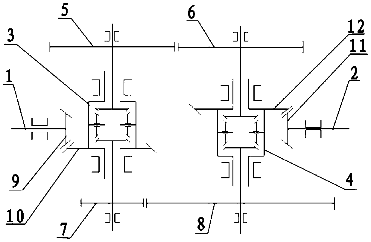
[0062] Both the first differential and the second differential are bevel gear differentials;

[0063] The transmission mechanism includes a first gear 5, a second gear 6, a third gear 7 and a fourth gear 8;

[0064] The input shaft 1 is connected to the first pot tooth 10 of the first differential through the first corner tooth 9;

[0065] The first gear 5 is arranged on one end away from the first pot tooth 10 of the first differential, and the second gear 6 meshed with the first gear 5 is arranged on an end close to the second pot tooth 12 of the second differential; The three gears 7 are arranged at one end close to the first basin teeth 10 of the first differential, and the fourth gear 8 meshed with the third gear 7 is arranged at one end away from the second basin teeth 12 of the second differential;

[0066] The output shaft 2 is connected to the second basin tooth 12 of the second differential through the second corner tooth 11;

[0067] The relationship that the inde...

Embodiment 2

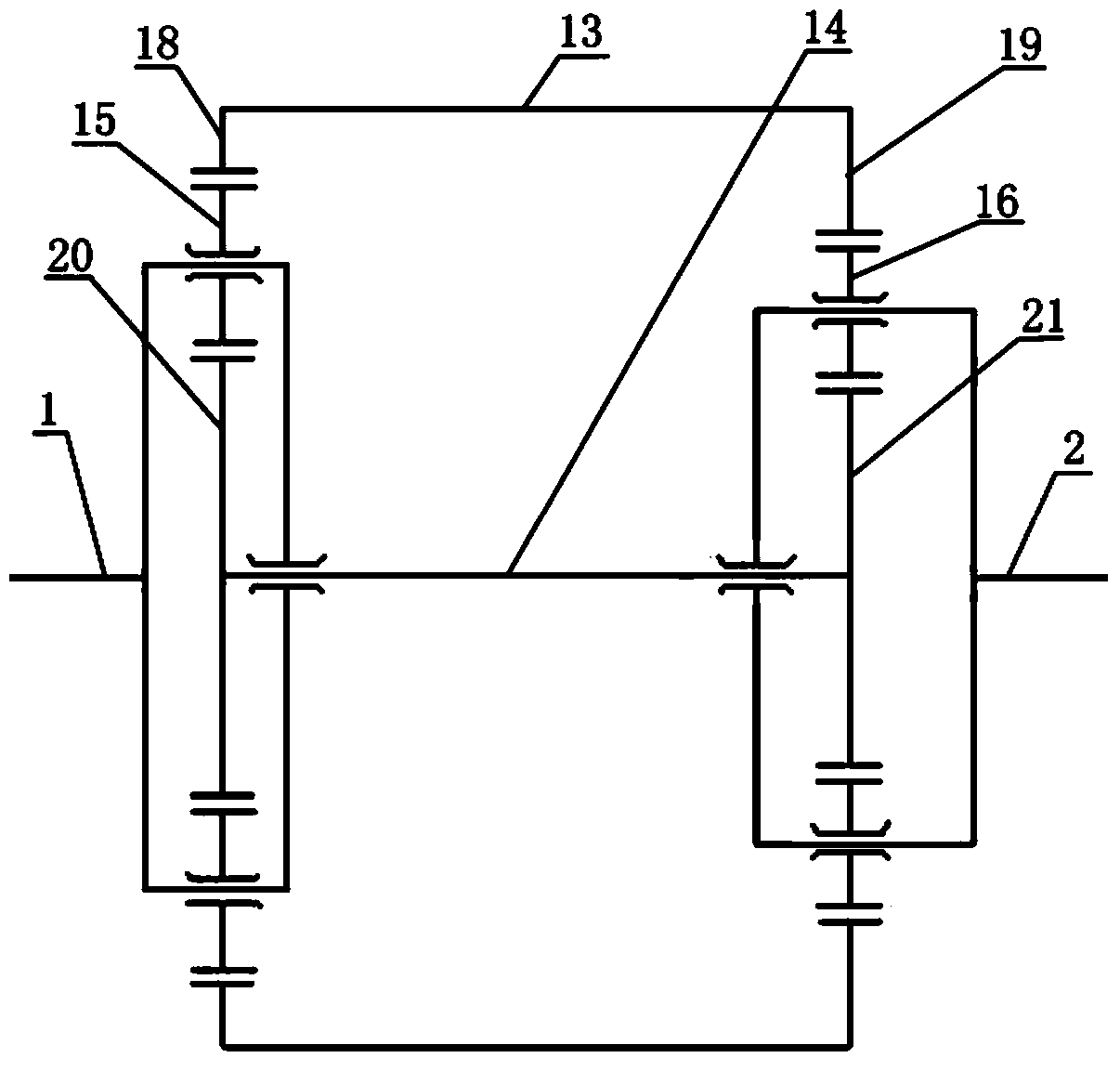
[0119] Such as figure 2 As shown, both the first differential and the second differential are sun gear differentials;

[0120] The transmission mechanism is the ring gear connection part 13 and the transmission shaft 14;

[0121] One end of the ring gear connecting portion 13 is fixedly connected to the first ring gear 18 of the first differential, and the other end is fixedly connected to the second ring gear 19 of the second differential;

[0122] One end of the drive shaft 14 is fixedly connected to the first sun gear 20 of the first differential, and the other end is fixedly connected to the second sun gear 21 of the second differential;

[0123] The input shaft 1 is connected to the first planetary gear 15 of the first differential, and the output shaft 2 is connected to the second planetary gear 16 of the second differential;

[0124] Pitch circle diameter n of the first sun gear 20 1 , The pitch circle diameter m of the first ring gear 18 1 , The pitch circle diame...

Embodiment 3

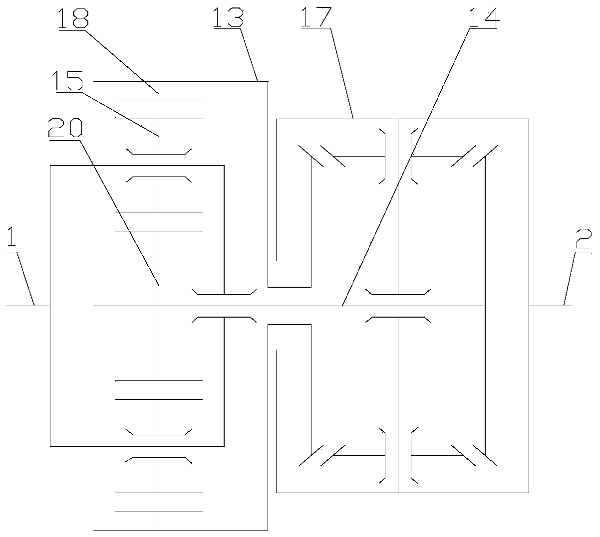
[0153] Such as image 3 As shown, the first differential is a sun gear differential, and the second differential is a bevel gear differential;

[0154] The transmission mechanism includes a ring gear connection part 13 and a transmission shaft 14;

[0155] One end of the ring gear connecting portion 13 is fixedly connected to the first ring gear 18, and the other end is fixedly connected to the side gear of the second differential;

[0156] One end of the drive shaft 14 is fixedly connected to the axis of the first sun gear 20, and the other end is fixedly connected to the other side gear of the second differential;

[0157] The input shaft 1 is connected to the first planetary gear 15, and the output shaft 2 is connected to the casing of the second differential;

[0158] Pitch circle diameter m of the first ring gear 18 1 Pitch circle diameter n of the first sun gear 20 1 The relationship is:

[0159] 01 / m 1 )1 / m 1 ) <1.

[0160] When the pitch circle diameter of th...


PUM


Abstract

The invention relates to the filed of transmission device, and in particular relates to a double differential type continuously variable transmission device. The double differential type continuously variable transmission device comprises an input shaft, an output shaft, a first differential mechanism, a second differential mechanism and a transmission mechanism, wherein the input shaft is connected with the first differential mechanism, the first differential mechanism is connected with the second differential mechanism through the transmission mechanism, the output shaft is connected with the second differential mechanism, and the transmission mechanism is a gear structure. According to the double differential type continuously variable transmission device provided by the invention, by using the two differential mechanisms and the transmission mechanism constituted by gear transmission, the real-time stepless speed change of the transmission device is achieved through simultaneously controlling the revolution speeds of one or more differential gears, and the design requirement of various kinds of cars on the range of transmission ratios is achieved through adjusting the transmission mechanism according to a certain rule; the problem that the speed change is slow in response and not sensitive enough is solved; the whole transmission process is performed completely by gears without any clutch and coupler device, so that the sliding ratio of the continuously variable transmission device is reduced, the bearable power output is increased, and the overload resistance and the shock resistance of the continuously variable transmission device are improved.

Description

technical field [0001] The invention relates to the field of transmissions, in particular to a double-differential continuously variable transmission. Background technique [0002] Existing continuously variable transmissions can generally be divided into three types: liquid transmission, electric transmission and mechanical transmission. [0003] There are two types of hydraulic transmission: one is the hydraulic type, which is mainly composed of pumps and motors or variable speed transmissions composed of valves and pumps, suitable for small and medium power transmissions. The other type is the hydraulic type, which uses a hydraulic coupling or hydraulic torque for variable speed transmission, and is suitable for high power (hundreds to thousands of kilowatts). The advantages of liquid transmission are: large speed range, can absorb shock and prevent overload, high transmission efficiency, long life, easy to realize automation, but it also has high manufacturing precision...

Claims


Application Information

Patent Timeline
IPC IPC(8): F16H3/76F16H57/023
CPCF16H3/76F16H57/023F16H57/08
Inventor 张宝山
Owner 张宝山
Learn More