Self-cooled thermal power acting method

A self-cooling, work-based technology, applied in heat pumps, refrigerators, refrigeration components, etc., can solve problems such as unimpeded exploration and thinking, large flow loss, energy waste, etc., to solve the problem of volume loss, high efficiency and low cost. cost effect

Inactive Publication Date: 2014-05-07
张玉良
View PDF6 Cites 11 Cited by
  • Summary
  • Abstract
  • Description
  • Claims
  • Application Information

AI Technical Summary

Problems solved by technology

[0002] The second law of thermodynamics is that the basic conclusions of thermodynamics have never been shaken, but following its law, the thermodynamic work system must discharge heat to a low-temperature heat source, which always causes huge energy waste. For example, the thermal efficiency of a single-cycle work process is only close to 50%, such as the thermal efficiency of a gas turbine. Less than 40%, although there are no questionable reports in the mainstream thermodynamics field, this does not stop people from exploring and thinking about it, especially in today's energy crisis and serious environmental damage, any possible breakthrough is very important
3. The traditional jet extractor has a large flow loss and low efficiency due to the throat zoom structure, and its structure and performance have a lot of room for improvement. In addition, it is simple and has no rotating parts, and the working medium is heated by the liquid pump force to generate power. The consumption of compression work is the smallest, that is, there is a lot of room for improvement in the performance of jet pumping refrigeration technology

Method used


Image

  • Self-cooled thermal power acting method
  • Self-cooled thermal power acting method
  • Self-cooled thermal power acting method

Examples


Embodiment approach 1

[0050] Embodiment 1, closed self-cooling thermodynamic cycle:

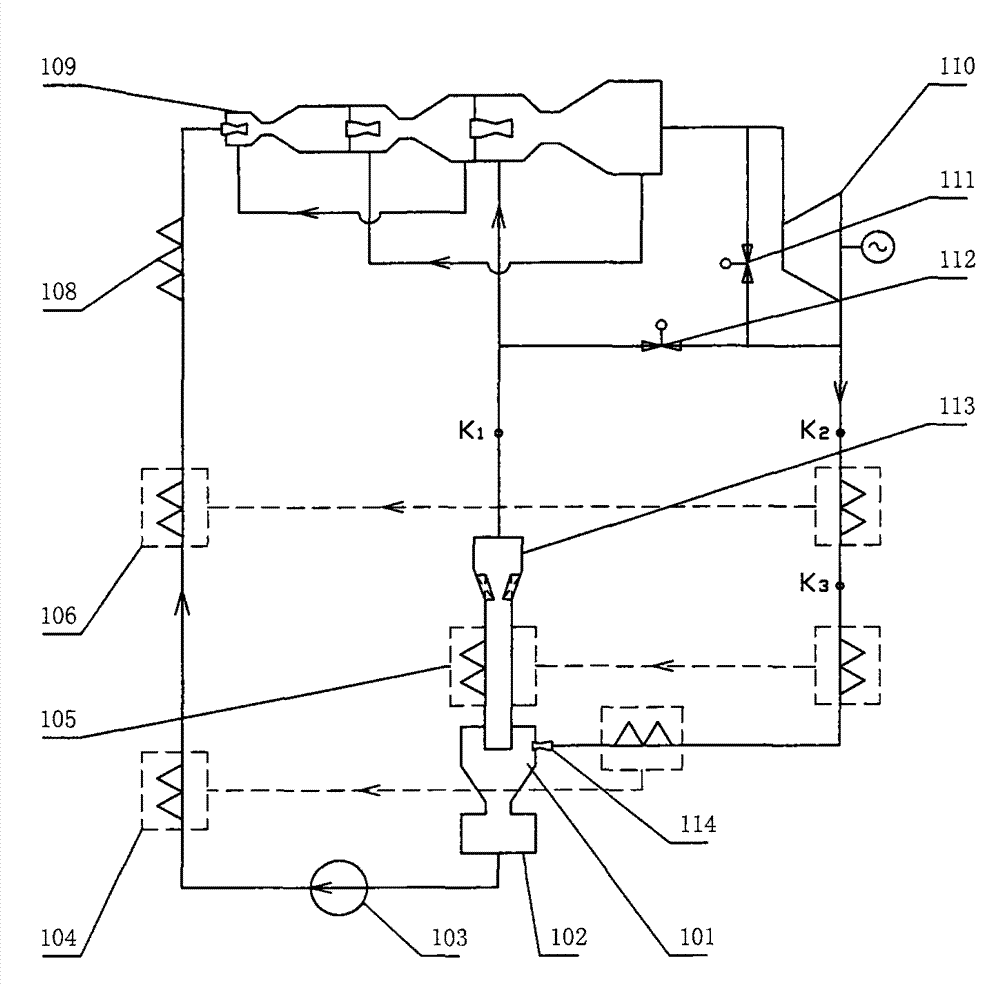
[0051] as attached figure 1 The closed self-cooling thermodynamic cycle shown uses the jet refrigeration liquefaction system 101 to realize the heat removal and liquefaction of the gas working medium, and uses the circulation jet extractor 109 and the gas turbine unit 110 (or other types of expanders) to form an expansion work system at the same time Provide pumping and injection power for the refrigeration liquefaction system, the working medium can generally be air, nitrogen, CO, whose boiling point is lower than normal temperature 2 Or a gas such as freon, or a high boiling point gas such as water vapor. Along the flow direction of the working medium indicated by the arrow, the liquid working medium produced by the refrigeration liquefaction system 101 is boosted by the pump 103, then passes through the recuperation heat exchangers 104, 105 and 106 to absorb heat, and then passes through the heater 108 to abso...

Embodiment approach 2

[0066] Embodiment 2, new jet extractor:

[0067] with attached figure 1 , attached Figure 5 and attached Image 6 The multi-stage cycle jet extractor used in the paper is different, as attached Figure 7Shown is a straight-through pipe swirl jet extractor. The injection and diffusion process abandons the traditional throat zoom structure and adopts a straight-through pipe (not limited to straight pipes with equal diameters, which can be gradually expanded or tapered) swirl injection. Among them, A is a schematic diagram of single-stage injection structure, B is a schematic diagram of porous injection, C and D are schematic diagrams of oblique swirling jets, and there is a flow guide device at the end, and E is a straight-through pipe swirling multi-stage circulating jet air extractor.

[0068] attached Figure 8A It is a split-type multi-stage serial circulation jet extraction system that adopts the combination of reheating method and gas turbine; Figure 8B The split ar...

Embodiment approach 3

[0071] Embodiment 3, self-cooling thermodynamic cycle using compression and cooling liquefaction:

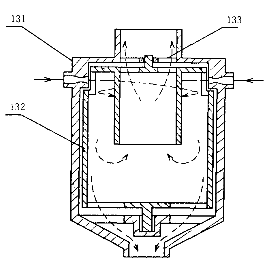
[0072] attached Figure 15 It is the two jet swirl heat exchange methods of the jet swirl heat exchange heat pump. The working medium absorbs heat from the low temperature environment or the low temperature working medium through expansion. Spray tangentially or obliquely into the cyclone through the nozzle, the spray process and the attached figure 2 The spray swirl shown is similar. After the high-speed jet cools down, it absorbs heat through the wall of the swirler and the external working fluid or environment, and then enters the exhaust pipe to be discharged. The exhaust pipe adopts a straight-through method or a deflector that increases the recovery swirl power. Way. Among them, the built-in exhaust pipeline of A can reduce the volume, and the exhaust pipeline of B can be designed with a large diameter to reduce resistance. The heat exchange process can be composed of a...


PUM


Abstract

The invention relates to a self-cooled thermal power acting method and belongs to the field of thermal energy power. A working medium of a thermal power system absorbs heat from a heat source to act. The self-cooled thermal power acting method includes the temperature rising process in which after the pressure of the working medium which is in a low temperature state is boosted and the working medium is heated, the working medium becomes a power air source, the expansion acting process carried out after the power air source enters an expansion acting system and the heat releasing process in which heat of the low-temperature gas working medium which carried out expansion acting is further released. The thermal power system achieves the thermal power circulating process from the temperature rising process, the expansion acting process, the heat releasing process and the temperature rising process. A thermal pump process is used for cooling or liquefying the gas working medium which carried out expansion acting. When heat is released in the thermal pump process, the temperature or the pressure parameter of the working medium is lower than the maximum parameter of the power air source. In the expansion acting process, partial or overall heat which is released in the thermal pump process is absorbed and common acting is carried out. A heat returning process is adopted, so that the heat released by the system is absorbed in the system heat absorbing process. An air energy engine with practicability is obtained, and high-efficiency thermal power circulation of all sorts is achieved. Meanwhile, the invention provides a novel jetting air ejector and a novel thermal pump optimizing system and cost is reduced.

Description

technical field [0001] The invention belongs to the field of thermal power. Background technique [0002] The second law of thermodynamics is that the basic conclusions of thermodynamics have never been shaken, but following its law, the thermodynamic work system must discharge heat to a low-temperature heat source, which always results in huge waste of energy. For example, the thermal efficiency of a single-cycle work process is only close to 50%, such as the thermal efficiency of a gas turbine. Less than 40%, although there are no questionable reports in the mainstream thermodynamics field, this does not stop people from exploring and thinking about it, especially in today's energy crisis and serious environmental damage, any possible breakthrough is very important. There are some solutions to realize the work done by a single heat source. Unfortunately, there are no practical cases. In summary, there are several solutions as follows: (1) Use heat pump to generate heat to ...

Claims


Application Information

Patent Timeline
Patent Type & Authority Applications(China)
IPC IPC(8): F01K27/00
CPCF01K25/00F25B30/00F04F5/22F04F5/44F25B27/00
Inventor 张玉良
Owner 张玉良
Why Eureka
Try Eureka