Eureka AIR delivers breakthrough ideas for toughest innovation challenges, trusted by R&D personnel around the world.

Hydraulic cutting, U-shaped hole slagging and gas treatment method

A hydraulic slotting and U-shaped technology, which is applied in gas discharge, earthwork drilling, safety devices, etc., can solve problems such as difficult slag discharge

Inactive Publication Date: 2014-05-07
CHINA UNIV OF MINING & TECH
View PDF7 Cites 2 Cited by
  • Summary
  • Abstract
  • Description
  • Claims
  • Application Information

AI Technical Summary

Problems solved by technology

[0003] Technical problem: The purpose of this invention is to solve the problem of difficult slag discharge when drilling along the coal seam, high-level roadway through the bed or low-level roadway through the layer in the underground roadway in actual production, and to provide a simple and convenient slag discharge. The hydraulic slotting gas control method has a large range of pressure relief and can effectively improve the safety and work efficiency of on-site operations

Method used


Image

  • Hydraulic cutting, U-shaped hole slagging and gas treatment method
  • Hydraulic cutting, U-shaped hole slagging and gas treatment method
  • Hydraulic cutting, U-shaped hole slagging and gas treatment method

Examples


example 1

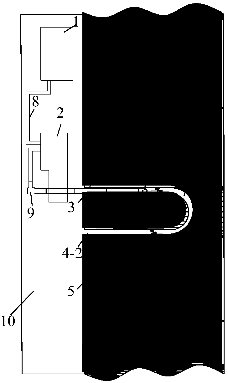
[0030] Such as figure 1 , figure 2 As shown, it is the slag discharge gas treatment of U-shaped drilling holes in the coal seam roadway along the bedding hole hydraulic slotting. Firstly, use a kilometer directional drilling rig to construct a U-shaped borehole 7 with a diameter of 94 mm along the coal seam in the roadway of the coal seam 5 to ensure that the distance between the two side boreholes 4-1 and the borehole 4-2 of the U-shaped borehole 7 is 6 ~8m, then the drilling rig 2 is connected to the hydraulic slotting system 1 through the high-pressure rubber hose 8, the drilling rig 2 is connected to the drill pipe 3 through the high-pressure water braid 9, and the other end of the 75mm drill pipe 3 is connected to the 50mm diameter slotting device 6; Drive the drill pipe 3 to send the slotting device 6 into the slotting drill hole 4-1 to the pre-cutting position, then start the hydraulic slotting system 1, and the high-pressure water flows out from the slotting system 1...

example 2

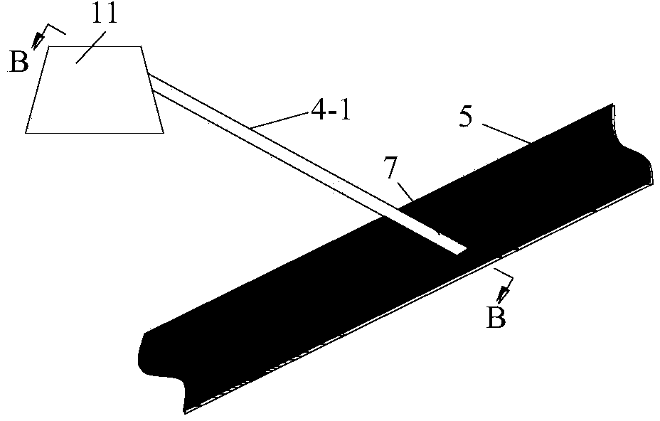
[0032] Such as image 3 , Figure 4 As shown, it is the slag and gas treatment of the high-level roadway 11 through the downhole hydraulic slotting U-shaped drilling 7, which is basically the same as the first example. The different parts are mainly from the high-level roadway 11 of the coal seam 5 to the lower coal seam 5. The hydraulic slotting is carried out in groups and sequentially. First, a U-shaped drill hole with a diameter of 94mm is constructed along the high-level roadway 11 to the lower coal seam 5 to ensure that the U-shaped drill hole has two The distance between side drilling holes is 6-8m, and the depth of U-shaped drilling reaches 3m from the coal seam floor. The remaining parts are the same as Example 1, and the same parts are omitted.

example 3

[0034] Such as Figure 5 , Image 6 As shown, it is the slag and gas treatment of the low-level roadway 12 through the upward hole hydraulic slotting U-shaped drilling 7, which is basically the same as the first embodiment. The different parts are mainly to implement hydraulic slotting in groups from the low-level roadway 12 through the layer to the upper coal seam 5. Firstly, a U-shaped drill hole with a diameter of 94mm is constructed along the low-level roadway 11 to the upper coal seam 5 to ensure that the U-shaped drill hole has two The distance between side drilling holes is 6-8m, and the depth of U-shaped drilling reaches 3m from the roof of the coal seam. The remaining parts are the same as Example 1, and the same parts are omitted.


PUM


Abstract

The invention provides a hydraulic cutting, U-shaped hole slagging and gas treatment method which is applicable to slagging during a process of applying a hydraulic cutting gas technology in drilling of a coal seam bedding, a high-position lane penetrating layer or a low-position lane penetrating layer. A U-shaped drilled hole is pre-constructed in a coal seam by use of a kilo directional drilling machine from the coal seam bedding, the high-position lane penetrating layer or the low-position lane penetrating layer to a target area coal body, and then a hydraulic cutting device is connected with a drill stem and is fed into one hole of the U-shaped drill hole by virtue of the drilling machine; the hydraulic cutting device is started, firstly hydraulic cutting is performed on the coal body in one hole of the U-shaped drilled hole, and draining and slagging is performed by virtue of the other drilled hole of the U-shaped drilled hole; when hydraulic cutting in one drilled hole is finished, hydraulic cutting is performedin the other drilled hole of the U-shaped drilled hole, and the previous drilled hole serves as a slagging hole. The method can be used for solving the problems of difficulty in slagging, hole blockage, hole spraying and the like in hydraulic cutting of the coal seam, further improving the air permeability of the coal seam, and eliminating the concentrated stresses of the coal body and wall rocks; great coal and gas outburst potential energy is released, so that an effective effect of preventing coal and gas outburst is achieved. The method is simple in operation, convenient in use and good in effect.

Description

technical field [0001] The invention relates to a hydraulic slit U-shaped hole slag discharge gas treatment method, which is especially suitable for slag discharge when the hydraulic slit gas technology is implemented in coal seam alignment, high-level roadway through-bed or low-level roadway through-bed drilling. Background technique [0002] my country's coal seams have the structural characteristics of microporosity, low permeability, and high adsorption. More than 95% of the high-gas coal seams and coal seams mined by outburst mines are high-gas and low-permeability coal seams. The mining of high-gas and low-permeability coal seams often leads to gas overruns, gas explosions, gas outbursts, and coal and gas outbursts in the working face, which seriously threaten the lives of coal miners. After entering the 21st century, with the high-efficiency intensification of coal production and the deepening of coal mining depth, the ground stress and gas pressure will increase, the...

Claims


Application Information

Patent Timeline
IPC IPC(8): E21F7/00
Inventor 翟成林柏泉彭深余旭向贤伟倪冠华李全贵许彦明
Owner CHINA UNIV OF MINING & TECH
Why Eureka
Eureka Blog
Learn More