Concrete engineering expansion joint vertical sealing up structure fixing member and application thereof

A technology of vertical water stop and concrete

Active Publication Date: 2014-05-07
中能建建筑集团有限公司
View PDF6 Cites 2 Cited by
  • Summary
  • Abstract
  • Description
  • Claims
  • Application Information

AI Technical Summary

Problems solved by technology

[0002] In existing concrete structures, such as retaining dams, reservoirs, subways, culverts, sluices, tunnels and other underground projects, due to the inability to pour continuously or the deformation of the foundation settlement (earthquake), or the concrete caused by temperature changes Due to thermal expansion and contraction of components, deformation joints and construction joints are often left during pouring. These gaps must take anti-leakage measures to prevent external water or groundwater from leaking into the structural space. Concrete grooves are set between the concrete and the second-stage concrete, and soft asphalt and copper sheets or rubber waterstops are installed in the grooves. However, this method requires prefabricated concrete grooves. The outer 3 sides are chiseled, which will prolong the construction period and increase labor. At the same time, because the length (height) of each concrete groove is generally only 50-100cm, the expansion gap must be composed of multiple concrete grooves, so multiple horizontal lines will be generated. The cracks and the irregular deformation of multiple concrete grooves will cause the leakage of soft asphalt in the subsequent pouring, and it is difficult to clean up; it is very effective to use channel steel instead of concrete grooves, but due to the pre-embedded fixings and connections The parts are designed as one piece, and the connecting parts should protrude out of the section during pouring, so it is difficult to construct the first-stage concrete section, and the connecting parts must be cut off along the section after pouring asphalt, resulting in waste

Method used


Image

  • Concrete engineering expansion joint vertical sealing up structure fixing member and application thereof
  • Concrete engineering expansion joint vertical sealing up structure fixing member and application thereof
  • Concrete engineering expansion joint vertical sealing up structure fixing member and application thereof

Examples


Embodiment 1

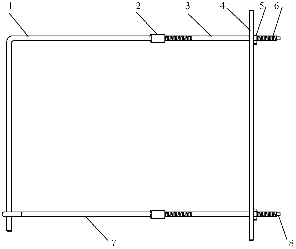
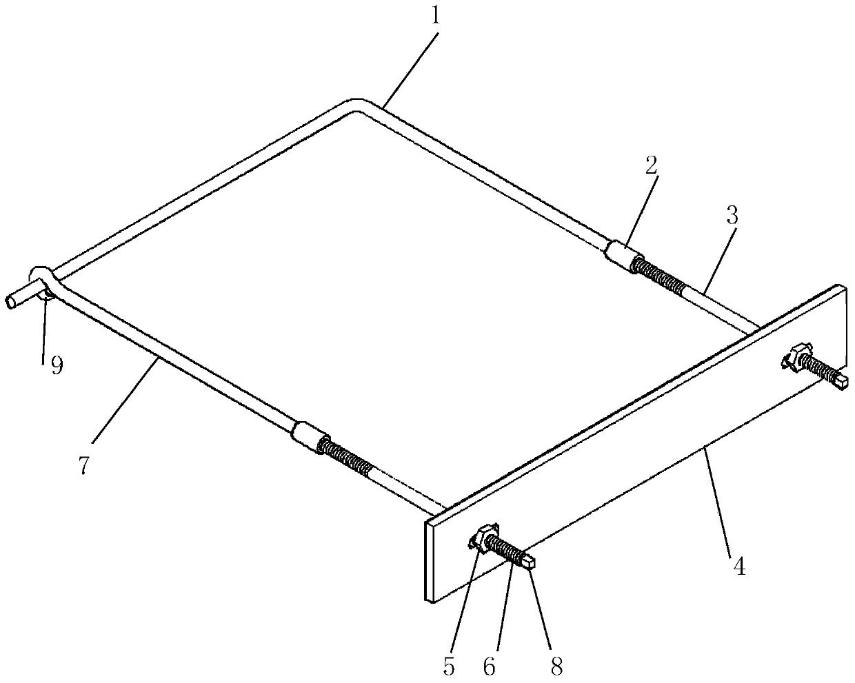
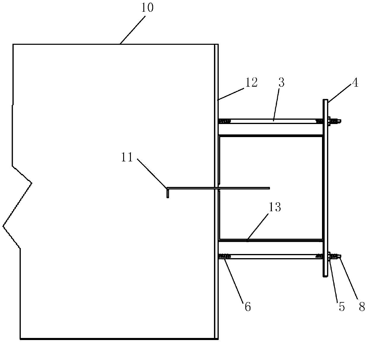
[0035] Embodiment 1, referring to the accompanying drawings: a vertical water-stop structure fixture for expansion joints in concrete engineering, including embedded parts A1, embedded parts B7, connectors 3, and flat irons 4. The embedded parts A1 are selected from 8- Made of 10mm steel bar, one end is provided with a connecting pipe 2, one end of the connecting pipe 2 is welded and fixed with the embedded part A1, and there is a thread inside, the embedded part A1 is bent 90° horizontally in the middle to form an L shape, and the embedded part A1 is The length of a section with connecting pipe 2 is 30-60cm, the length of the bent part is 20-50cm or set according to the width of the concrete section at the supporting place, so as not to exceed the width of the section. One end of the embedded part B7 is welded with the ring 9 and then bent Arc, the other end is provided with a connecting pipe 2, the length of the embedded part B7 is 30-60cm, and a section of the connecting pip...


PUM


Abstract

The invention relates to an underground (underwater) building waterproof device and particularly relates to a concrete engineering expansion joint vertical sealing up structure fixing member and an application thereof. The concrete engineering expansion joint vertical sealing up structure fixing member comprises a U-shaped embedded part formed by an embedded part A and an embedded part B, wherein the embedded part is provided with a connection pipe, the connection pipe is provided with an inner thread and is in threaded connection with a connection member, slab iron is fixed to the connection member through a nut into a whole so as to fix a vertical sealing up steel channel at the position of a concrete fracture surface, asphalt is poured into the steel channel, and the connection member and the slab iron are disassembled after cooling and maintained and collected for recycle. By means of the concrete engineering expansion joint vertical sealing up structure fixing member, the problem of water seepage caused by differential settlement or diastrophism of strata in water conservancy projects can be solved, manual work can be saved, construction periods are shortened, and resources are saved.

Description

technical field [0001] The invention relates to an underground (underwater) building waterproof device, in particular to a vertical water-stop structure fixture for expansion joints in concrete engineering and its application. Background technique [0002] In existing concrete structures, such as retaining dams, reservoirs, subways, culverts, sluices, tunnels and other underground projects, due to the inability to pour continuously or the deformation of the foundation settlement (earthquake), or the concrete caused by temperature changes Due to thermal expansion and contraction of components, deformation joints and construction joints are often left during pouring. These gaps must take anti-leakage measures to prevent external water or groundwater from leaking into the structural space. Concrete grooves are set between the concrete and the second-stage concrete, and soft asphalt and copper sheets or rubber waterstops are installed in the grooves. However, this method require...

Claims


Application Information

Patent Timeline
Patent Type & Authority Applications(China)
IPC IPC(8): E02B3/16E02D29/16E21D11/38
Inventor 张朝利
Owner 中能建建筑集团有限公司
Why Eureka
Try Eureka