Method for attaching panel and apparatus therefor

A technology for sticking devices and panels, applied in the directions of bonding methods, adhesives, instruments, etc., can solve problems such as difficulty in overflow control and poor control, and achieve the effect of shortening the bonding time.

Inactive Publication Date: 2014-05-07
PANASONIC INTELLECTUAL PROPERTY MANAGEMENT CO LTD
View PDF4 Cites 1 Cited by
  • Summary
  • Abstract
  • Description
  • Claims
  • Application Information

AI Technical Summary

Problems solved by technology

[0017] In the case of the inversion method, the ultraviolet curable resin is diffused radially from the center in all directions, thereby expelling air bubbles and laminating, but it is difficult to control the overflow of the ultraviolet curable resin especially on the long side, and there will be the following Occurrence of defects: The defect that the ultraviolet curable resin overflows beyond the dam and overflows out of the filling area; the defect that air is trapped in the diffusion of the ultraviolet curable resin, resulting in residual air bubbles in the bonding surface

Method used


Image

  • Method for attaching panel and apparatus therefor
  • Method for attaching panel and apparatus therefor
  • Method for attaching panel and apparatus therefor

Examples


Embodiment approach 1)

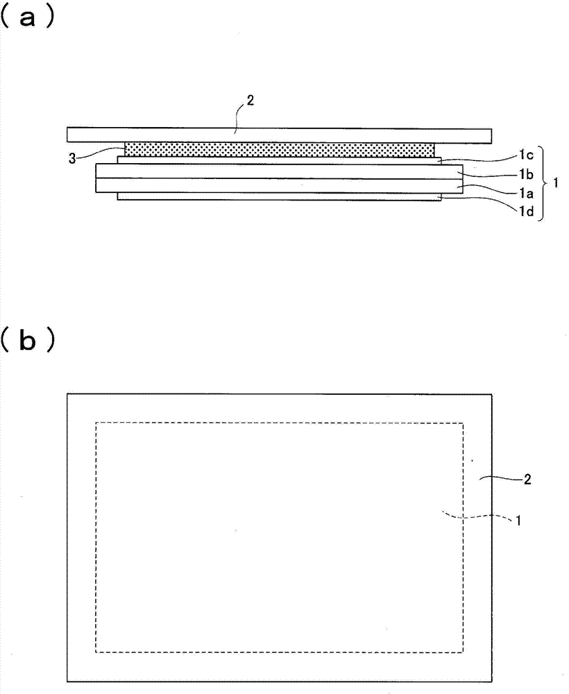
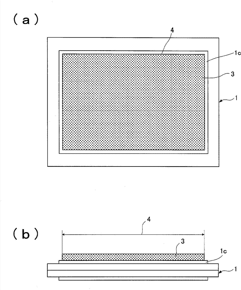
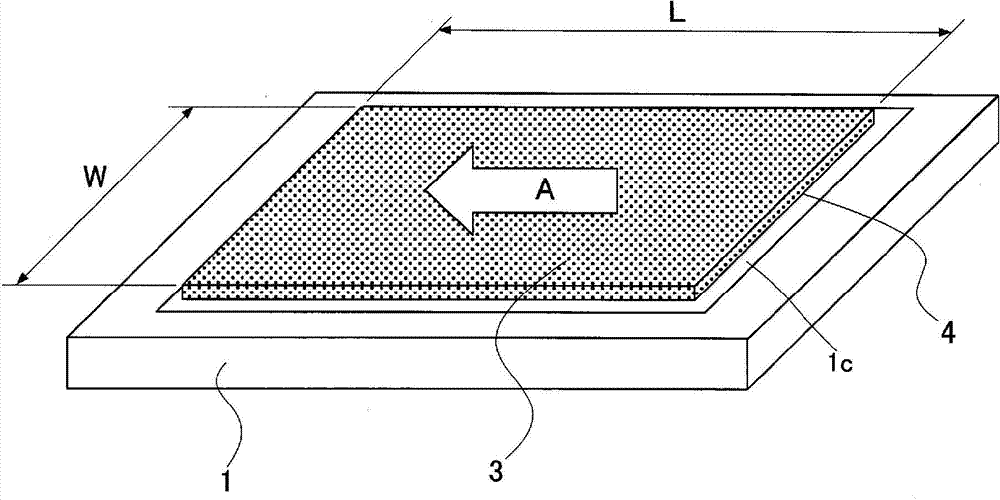
[0062] Figure 1 ~ Figure 7 This shows Embodiment 1 of the present invention.

[0063] Here, as figure 1 (A) (b) The case where the transparent touch panel (hereinafter referred to as touch panel) 2 and the liquid crystal display panel 1 are bonded with the ultraviolet curable resin 3 to manufacture a liquid crystal display module with a touch panel will be described. .

[0064] The liquid crystal display panel 1 as the first panel has a structure in which liquid crystal is enclosed between an array substrate 1a and a color filter substrate 1b, and an upper polarizing plate 1c and a lower polarizing plate 1d are attached to both surfaces, respectively. In addition, although not shown, a driver integrated circuit, a flexible substrate, etc. are mounted.

[0065] The touch panel 2 as the second panel has a structure in which a transparent electrode having conductivity is arranged on a glass substrate in order to detect a position touched by a user.

[0066] The resin 3 is a colorless ...

Embodiment approach 2)

[0111] Figure 8 ~ Figure 13 This shows Embodiment 2 of the present invention.

Embodiment approach 2

[0112] In the second embodiment, a case of bonding a protective panel to an organic EL device will be described.

[0113] Figure 8 (A) and (b) represent the monomer of the completed organic EL device.

[0114] The organic EL device 8 applies a phenomenon in which the organic substance emits light by applying a voltage to the organic substance, and has the following structure: an organic EL layer 8b is formed on the lower substrate 8a, and the organic EL layer 8b sandwiches the organic substance between two electrodes, It is formed by superimposing the film. In order to protect the organic EL layer 8b from humidity, impact, etc., it is covered with the upper substrate 8c via the resin 8d.

[0115] The lower substrate 8a uses glass with a thickness of 0.7 mm and a square with a size of 100 mm. The size of the organic EL layer 8b is 80 mm square, and the film thickness is several millimeters. Electrodes (not shown) are arranged on the lower substrate 8a. The upper substrate 8c uses ...


PUM


Abstract

The invention provides a method for attracting a panel and an apparatus therefor. A first panel (1) and a second panel (2) are bonded. The whole surface of the first panel (1) is coated into a rectangle with resin (3). At the same time, one pair of edges (L1 and L2) and another pair of edges (W1 and W2) relative to the periphery of the resin (3) are respectively higher than a coating surface (4a) inside the resin (3), and through coating, the heights of the edges (L1 and L2) are different from the heights of the edges (W1 and W2). The periphery of the overall-coated resin (3) is half solidified. Then, the first panel (1) and the second panel (2) are enabled to be opposite to each other, and after the first panel (1) and the second panel (2) are tightly bonded, all the resin (3) is fully solidified.

Description

Technical field [0001] The present invention relates to a method for bonding the entire surface of a first panel and a second panel using resin. [0002] Specifically, the bonding of the touch panel and the display panel, the bonding of the protective panel to the organic EL device, etc. can be given as examples. The display panel is a flat panel display, such as a liquid crystal display device, a plasma display, an organic EL panel, and the like. Background technique [0003] In recent years, as a method of arranging a transparent touch panel on a display panel, a method of bonding the entire surface of the display panel and the transparent touch panel with a liquid adhesive has gradually become the mainstream. [0004] By filling the gap between the display panel and the transparent touch panel with a transparent liquid adhesive whose refractive index is close to that of glass and acrylic, it enables the use of light reflection and refraction at the air layer interface between the...

Claims


Application Information

Patent Timeline
Patent Type & Authority Applications(China)
IPC IPC(8): C09J5/00
CPCG06F3/041G06F3/0412G06F2203/04103
Inventor 小山雅义秋月诚
Owner PANASONIC INTELLECTUAL PROPERTY MANAGEMENT CO LTD
Why Eureka
Try Eureka