
Gas cutting tool capable of guaranteeing circular degree

A gas cutting and tool technology, applied in the field of gas cutting tools, can solve the problems of affecting the cutting roundness of circular workpieces, unable to identify plates, secondary cutting of workpieces, etc., and achieve the effects of saving raw materials, simple and convenient positioning, and improving quality

Inactive Publication Date: 2014-05-07
ZHEJIANG GEELY POWERTRAIN CO LTD +4
View PDF9 Cites 3 Cited by
  • Summary
  • Abstract
  • Description
  • Claims
  • Application Information

AI Technical Summary

Problems solved by technology

[0004] The present invention mainly provides a gas cutting circle tool that can not only ensure the roundness of the workpiece but also ensure the effectiveness of cutting when using an ordinary gas cutting torch to manually cut a circular workpiece, which solves the problem of manual cutting of circular workpieces in the prior art. It is impossible to identify whether the plate is cut through when forming the workpiece, so it is very easy for the workpiece to be cut twice, which not only affects the cutting roundness of the circular workpiece, but also directly leads to technical problems such as poor cutting quality and low efficiency

Method used


Image

  • Gas cutting tool capable of guaranteeing circular degree
  • Gas cutting tool capable of guaranteeing circular degree
  • Gas cutting tool capable of guaranteeing circular degree

Examples


Embodiment

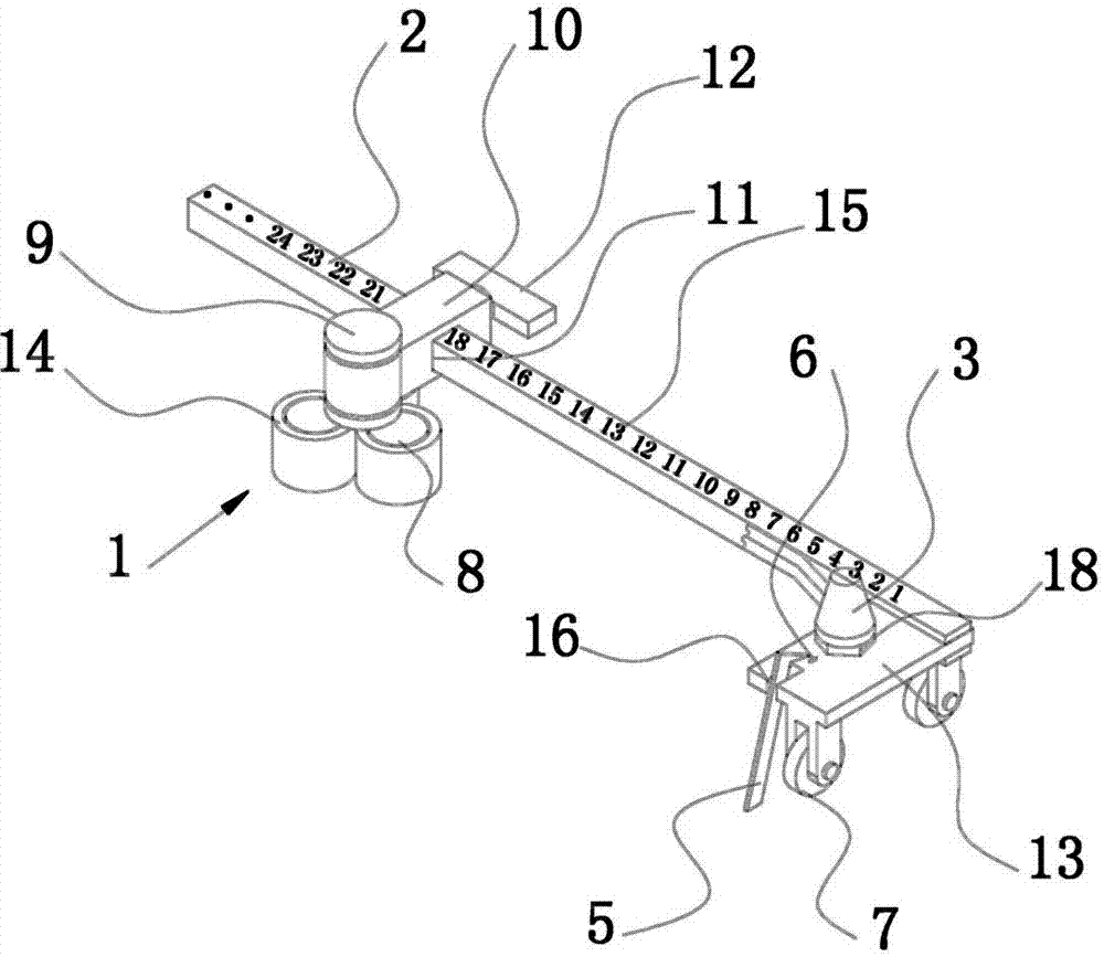
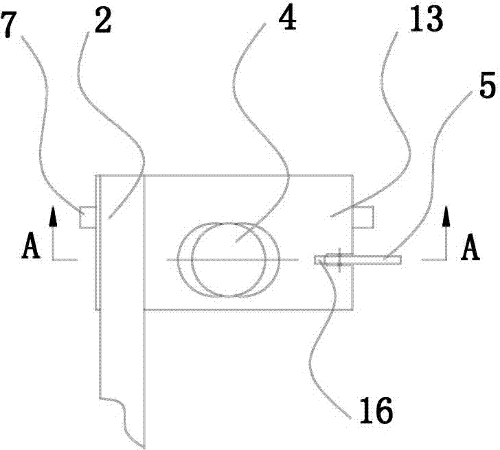
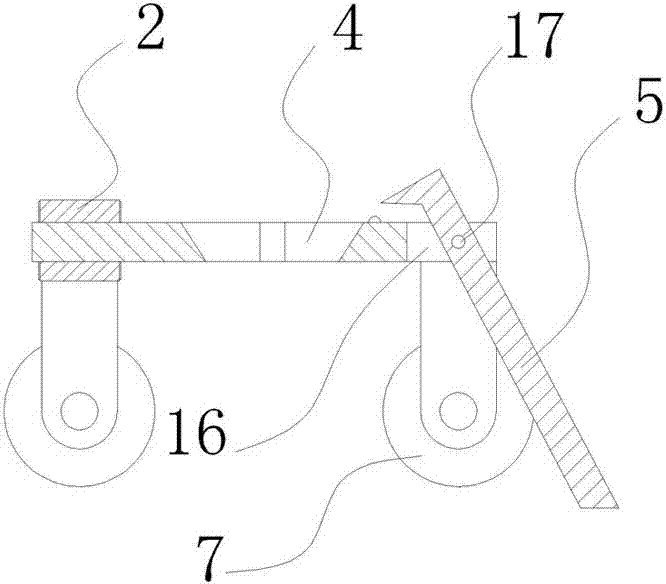
[0026]When in use, fix the positioning seat 1 on the surface of the plate with a thickness of 20 mm, adjust the support arm 2 back and forth to the radius length of the cut circular workpiece, and adjust the adjustment nut 18 to keep the torch head 3 and the surface of the plate at a suitable distance. After igniting the torch head 3 and plugging its burning end downward into the middle positioning hole 4 of the torch head to start gas cutting, then turn the support arm 2 counterclockwise at a constant speed, the pull plate 5 is inserted into the gas cutting slit and synchronized with the support arm 2 Move, when the plate is not cut through, the pull plate 5 runs blocked and rotates upwards, and then the pull plate 5 upper end triggers the sensor 6 downwards, and the sensor 6 sends a signal to cut off the oxygen source and the gas source of the torch head 3 immediately.

[0027] The specific embodiments described herein are merely illustrative of the concepts of the present in...


PUM


Abstract

The invention discloses a gas cutting tool and provides a gas cutting tool capable of guaranteeing the circular degree. According to the gas cutting tool capable of guaranteeing the circular degree,when a common gas cutting torch is used for cutting a circular workpiece manually, not only can the circular degree of the workpiece be guaranteed, but also cutting effectiveness can be guaranteed, and the technical problems that in the prior art, whether a plate is cut through cannot be recognized when the circular workpiece is cut manually, accordingly secondary cutting for the workpiece is needed, the cutting circular degree and cutting quality of the workpiece are poor and efficiency is low are solved. The gas cutting tool comprises a locating base and a supporting arm connected to the locating base horizontally and rotatably, wherein a cutting torch head of the gas cutting torch is fixed to the supporting arm and communicated with an oxygen source and a fuel gas source, a plurality of cutting torch head location holes are transversely distributed in the supporting arm, the combustion end of the cutting torch head is inserted downwards into the cutting torch head location holes, a pull plate capable of rotating up and down is rotatably connected with the edge of the rolloff side of the supporting arm, one end of the pull plate extends downwards and penetrates through a gas cutting seam formed by the cutting torch head in the workpiece, the other end of the pull plate extends to the upper portion of the supporting arm, a sensor is arranged on the upper surface, corresponding to the pull plate, of the supporting arm, and the pull plate controls connection and disconnection of the oxygen source and the fuel gas source of the cutting torch head through the sensor.

Description

technical field [0001] The invention relates to a gas cutting tool, in particular to a circular gas cutting tool which can manually cut circular workpieces with an ordinary gas cutting torch and can ensure the roundness of the workpiece and the cutting effectiveness. Background technique [0002] Gas cutting is a thermal cutting that uses the flame separation material produced by the mixed combustion of combustible gas and oxygen, also known as oxygen cutting or flame cutting. During gas cutting, the flame preheats the material to the ignition point at the starting point of the cutting, and then injects an oxygen flow to oxidize and burn the metal material violently, and the generated oxide slag is blown away by the air flow to form a cut. At present, gas cutting mainly adopts gas cutting machine, semi-automatic gas cutting machine, profiling gas cutting machine, photoelectric tracking gas cutting machine, numerical control cutting machine, etc., but the above equipment is n...

Claims


Application Information

Patent Timeline
IPC IPC(8): B23K7/10
CPCB23K7/107
Inventor 黄财明李立国邢艳红孙艳陈杰王瑞平
Owner ZHEJIANG GEELY POWERTRAIN CO LTD
Learn More