Metering pumps

A technology for metering pumps and pump chambers, applied in the direction of pumps, pump components, variable capacity pump components, etc., can solve the problems that hinder the compact structure of metering pumps, and achieve the effects of being conducive to manufacturing, simple fluid connection, and compact structure

Inactive Publication Date: 2016-11-30
THOMAS MAGNETE GMBH
View PDF8 Cites 0 Cited by
  • Summary
  • Abstract
  • Description
  • Claims
  • Application Information

AI Technical Summary

Problems solved by technology

Disadvantage is having a fluid channel around the sealed cylinder, which prevents the compact construction of the metering pump

Method used


Image

  • Metering pumps
  • Metering pumps

Examples


Embodiment Construction

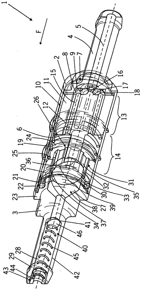
[0021] figure 1 The first embodiment of the metering pump 1 constructed as a reciprocating plunger pump is shown, including an inlet piece 2 forming a housing and an outlet piece 3 inserted into the inlet piece 2 along the longitudinal direction. The inlet piece 2 and the outlet piece 3 are rotating bodies and are concentrically oriented with each other and form a common axis A, which distributes the conveying direction (also referred to as the operating direction) F of the pump 1 from the inlet piece 2 to the outlet piece 3. The inlet side of the inlet 2 has an inlet connector 4 with an inlet channel 5. In order to connect to the piping system, the inlet nozzle 4 has a thickened inlet nozzle 4 nozzle. In the sleeve section on the outlet side, the inlet piece 2 is formed as a hollow cylinder, and a cylinder pump chamber 6 is arranged in its inner cavity. The pump driving device is arranged on the outside of the inlet 2 and the electromagnetic coil unit formed by the coil and t...


PUM


Abstract

The invention relates to a metering pump whose object is to allow simple metering of fluids, with an increased service life and a compact construction. It is characterized in that the piston rod (12) is functionally connected with the control body (30) having a surrounding sealing area (37), the inner circumference of the sealing cylinder (20) radially surrounds the sealing area (37), and the side of the piston rod and the sealing area ( 37) at least segmentally adjoining the balancing zone (39) at a distance from the sealing cylinder (20) radially farther than the sealing zone (37), and the control body (30) exceeds in the operating direction (F) of the actuator (10) The fluid connection is at least mainly disconnected behind the control edge (34).

Description

Technical field [0001] The invention relates to a metering pump. Background technique [0002] DE 10 2004 028 889 A1 shows a metering pump comprising a sealed cylinder, a piston rod that can move axially in the sealed cylinder, a discharge valve housing and a discharge valve body arranged on the outlet side of the sealed cylinder. The sealing cylinder has a flange facing the inside at its end on the outlet side, the flange having an edge that is turned toward the radial plane of the discharge valve housing, which edge forms the valve seat of the valve body. The sealing cylinder forms and includes a transfer chamber, wherein a spring provided in the transfer chamber is supported on a flange. The other end of the spring is supported on the piston rod and pretensions the piston rod against the conveying direction (also called the operating direction). The inlet side of the cylinder part is provided with axially distributed slits for fluid connection from the pump chamber to the de...

Claims


Application Information

Patent Timeline
Patent Type & Authority Patents(China)
IPC IPC(8): F04B13/00F04B53/14F04B53/16
Inventor 罗伯特·韦尔尼茨迈克·赫克阿克塞尔·穆勒迈克尔·穆勒安德列亚斯·门前
Owner THOMAS MAGNETE GMBH
Why Eureka
Try Eureka