
A ceramic circuit board fixture for electroplating

A ceramic circuit board and fixture technology, applied in the electrolysis process, electrolysis components and other directions, can solve the problem of broken circuit boards and other problems, and achieve the effect of increasing the area, convenient operation and strong practicability

Inactive Publication Date: 2016-09-21
广东达进电子科技有限公司
View PDF8 Cites 0 Cited by
  • Summary
  • Abstract
  • Description
  • Claims
  • Application Information

AI Technical Summary

Problems solved by technology

However, due to the small size of the ceramic circuit board and its brittle quality, the existing ceramic circuit board fixtures are prone to defects such as pinching the circuit board when clamping the circuit board for electroplating and thickening copper.

Method used


Image

  • A ceramic circuit board fixture for electroplating
  • A ceramic circuit board fixture for electroplating
  • A ceramic circuit board fixture for electroplating

Examples


Embodiment Construction

[0022] The present invention will be further described below in conjunction with accompanying drawing:

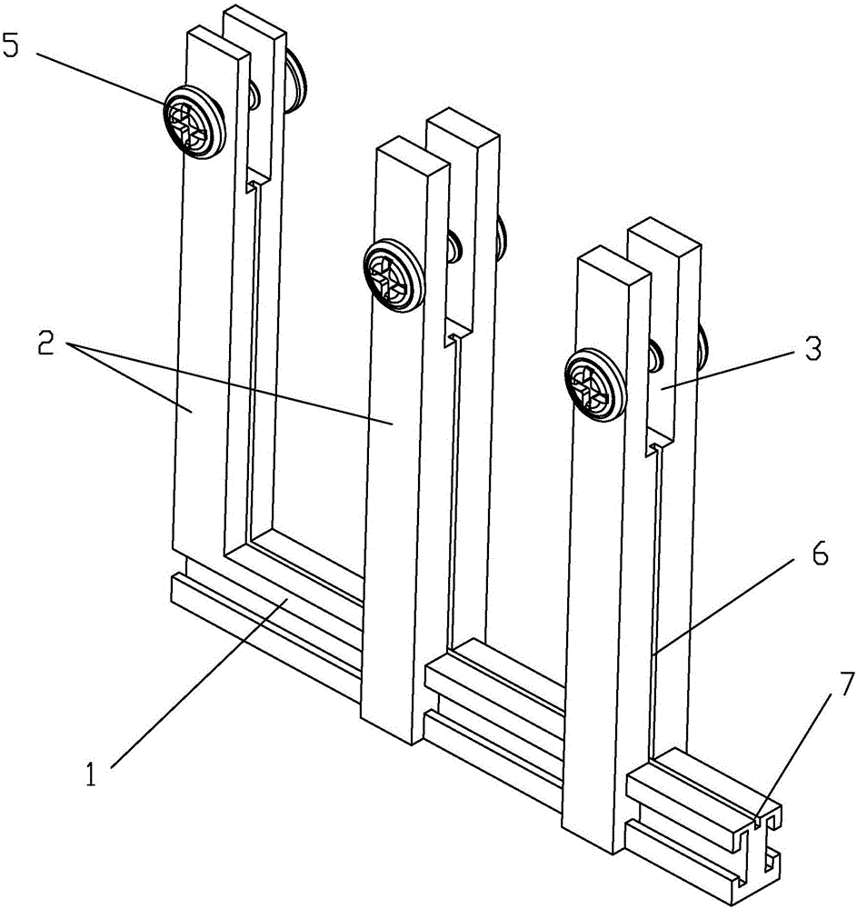
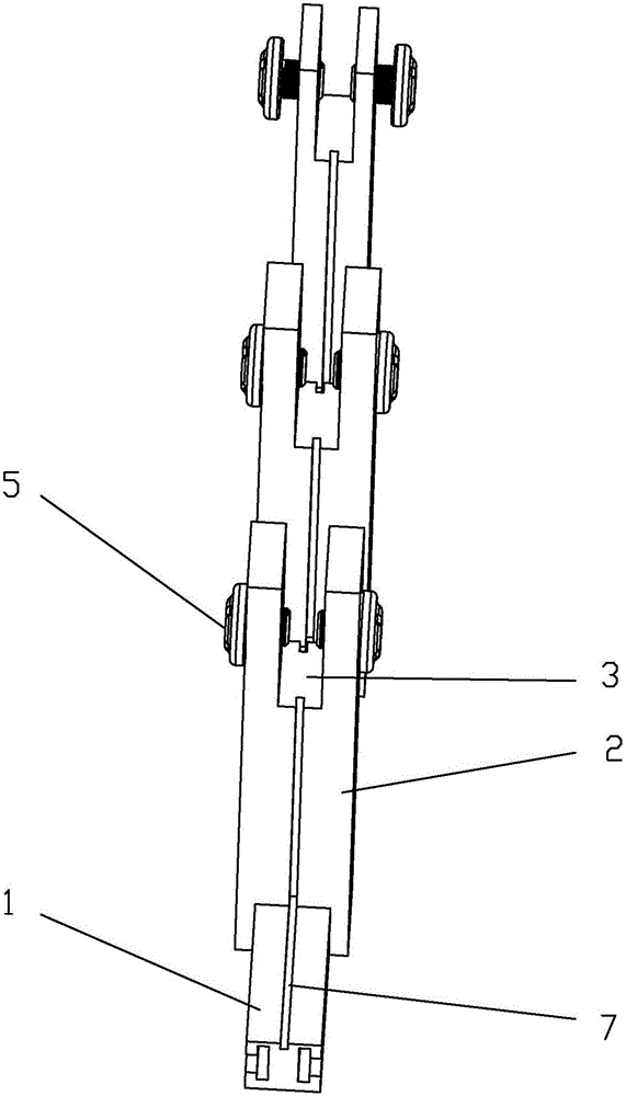
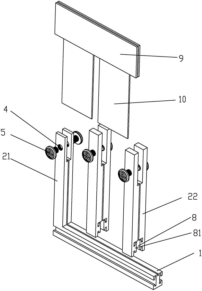
[0023] A ceramic circuit board fixture for electroplating, comprising a bottom plate 1, a plurality of splints 2 are vertically arranged on the bottom plate 1, and edge strip slots 3 for placing conductive edge strips 9 are arranged on the upper ends of the splints 2. The side of the clamping plate 2 is provided with a vertical clamping plate shallow groove 6 communicating with the side bar slot 3 for inserting the side of the ceramic circuit board 10, and the splint 2 on both sides of the side bar slot 3 is provided with threaded holes 4, so The threaded hole 4 is provided with an adjustable screw 5 that presses against the side of the conductive strip 9 to clamp the ceramic circuit board 10 .

[0024] During use, first clean the surface of the ceramic circuit board 10, then put the ceramic circuit board 10 into the shallow groove 6 of the vertical clamping plate of the fi...


PUM


Abstract

The invention discloses a ceramic circuit board clamp used for electroplating. The key point of the technical scheme is that the ceramic circuit board clamp comprises a baseplate, wherein a plurality of clamp plates are vertically arranged on the baseplate; an edge strip clamping groove used for placing a conductive edge strip is formed in the upper end of each clamp plate; a vertical chuck plate shallow groove communicated with the edge strip clamping groove and used for allowing the side part of a ceramic circuit board to be inserted into is formed in the side surface of the clamp plate; threaded holes are formed in the clamp plates on two sides of edge strip clamping grooves; adjustable screws used for pressing the sides of the conductive edge strips to clamp the ceramic circuit board are arranged in the threaded holes; the clamp plate can be processed into a movable clamp plate moving along the baseplate, so that ceramic circuit boards with different sizes can be clamped; the structure is simple; the operation is convenient. According to the ceramic circuit board clamp, as the adjustable screws are used for pressing the conductive edge strips and the two conductive edge strips are adopted to clamp the ceramic circuit board, the clamping area is increased; the problems in an electroplating process that the ceramic circuit board is damaged by an electroplating clamp or broken and dropped into an electroplate liquid due to vibration of equipment in a product line can be prevented.

Description

【Technical field】 [0001] The invention relates to a fixture for a circuit board, in particular to a fixture for electroplating a ceramic circuit board. 【Background technique】 [0002] Because ceramic circuit boards have good thermal conductivity, heat dissipation, corrosion resistance and high temperature resistance, they can effectively reduce the impact of solid waste on the environment caused by the overheating of LED lamps and the aging of carrier boards. Used in LED TV, LED computer, LED street lamp / tunnel lamp, LED landscape lighting and other fields. The high thermal conductivity ceramic circuit board as the carrier of LED lamps, due to the rapid development of the LED industry, the market demand for ceramic boards is also increasing, and the market prospect of ceramic circuit boards is very broad. Therefore, the PCB industry is paying more and more attention to the processing and production of ceramic circuit boards, further increasing investment, expanding producti...

Claims


Application Information

Patent Timeline
Patent Type & Authority Patents(China)
IPC IPC(8): C25D17/08C25D7/00
Inventor 陈华巍谢兴龙姚超
Owner 广东达进电子科技有限公司
Learn More