Gypsum needle type stirrer

A mixer and pin-type technology, applied in the field of pin-type mixers, can solve problems such as uneven mixing

Inactive Publication Date: 2021-03-19
泰山石膏(河南)有限公司
View PDF14 Cites 2 Cited by
  • Summary
  • Abstract
  • Description
  • Claims
  • Application Information

AI Technical Summary

Problems solved by technology

[0002] When the existing needle mixer mixes the gypsum powder, it generally only relies on the stirring needle to cut and mix. This method of mixing will cause uneven mixing due to the small number of material divisions. Therefore, we propose a gypsum needle mixer. Solve the above technical problems

Method used


Image

  • Gypsum needle type stirrer
  • Gypsum needle type stirrer
  • Gypsum needle type stirrer

Examples


Embodiment 1

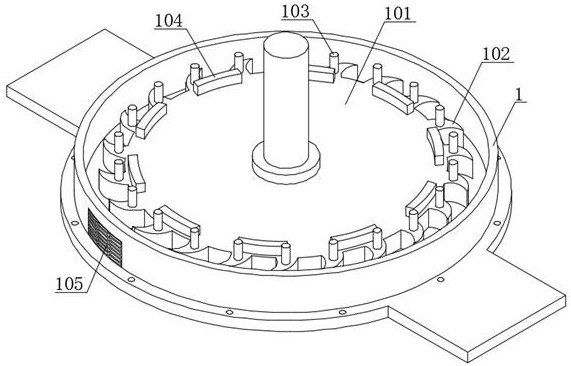
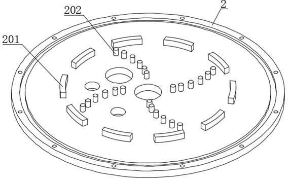
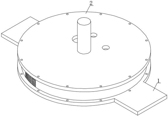
[0030] Example 1 please refer to figure 1 The embodiment shown in -4 is a gypsum pin mixer, which includes a base 1 and an upper cover 2 fastened to the base 1. Both the upper cover 2 and the base 1 are fixed, and the base 1 is rotatably connected with a turntable. 101, the middle part of the turntable 101 is a rotating shaft, which runs through the upper cover 2 and is connected to the external rotating power device, which drives the turntable 101 to rotate at a high speed, and the outer edge of the turntable 101 is provided with cutting arc teeth 102 in a circular array, and the cutting The material arc teeth 102 are fixedly connected with an external stirring needle 103, the rotating disk 101 is fixedly connected with an outer retaining ring 104 in a spaced shape, and the upper cover 2 is fixedly connected with an inner retaining ring 201 in a spaced shape, and the inner retaining ring 201 and The outer retaining ring 104 is cut off in the vertical direction, and the partit...

Embodiment 2

[0033] Example 2 please refer to Figure 5 In the illustrated embodiment, the same parts will not be repeated. The inner retaining ring 201 and the outer retaining ring 104 are separated in the horizontal direction, and the horizontal partition gap is larger than the gap between the inner retaining ring 201 and the outer retaining ring 104, which can make the material quickly Outflow, the diameter of the inner ring of the outer retaining ring 104 is greater than the diameter of the outer ring of the inner retaining ring 201, the gap between the two is 3-5 mm, preferably 3 mm, this gap is to further limit the material output granularity.

[0034] The material can flow out through the slit of the inner retaining ring 201, and is cut by the rotating outer retaining ring 104 when between the inner retaining ring 201 and the outer retaining ring 104, and the cutting work is completed.

Embodiment 3

[0036] Example 2 please refer to Figure 6 In the illustrated embodiment, the same parts will not be repeated. The inner retaining ring 201 and the outer retaining ring 104 are separated in the inclined direction. Outflow quickly, the diameter of the inner ring of the outer retaining ring 104 is greater than the diameter of the outer ring of the inner retaining ring 201, the gap between the two is 3-5 mm, preferably 3 mm, this gap is for further restriction The output granularity of the material.

[0037] The material can flow out through the slit of the inner retaining ring 201, and is cut by the rotating outer retaining ring 104 when between the inner retaining ring 201 and the outer retaining ring 104, and the cutting work is completed.


PUM


Abstract

The invention discloses a gypsum needle type stirrer, comprising a base and an upper cover buckled on the base. A rotating disc is rotatably connected in the base; spaced outer check rings are fixedlyconnected to the rotating disc; spaced inner check rings are fixedly connected to the upper cover; the inner check rings and the outer check rings are coaxial; and the diameter values of the inner rings of the outer check rings are greater than those of the outer rings of the inner check rings. The gypsum needle type stirrer has the beneficial effects that by arranging the interrupted inner checkrings and outer check rings, when the rotating disc rotates at a high speed, the rotating disc drives the outer check rings to rotate, at the moment, materials located on the rotating disc can flow to the exteriors of the outer check rings through a gap between the inner check rings, and at the moment, a small gap reserved between the outer check rings and the inner check rings, so that a cuttingchannel is formed; the rotating outer check rings cut the materials again; a cutting procedure is added, so that the materials can be stirred more sufficiently; and the situation that hard materialsare broken due to the fact that a gap between the rotating disc and the upper cover is too small is avoided by removing a stirring needle in the middle of an original rotating disc.

Description

technical field [0001] The invention relates to the field of needle mixers, in particular to a gypsum needle mixer. Background technique [0002] When the existing needle mixer mixes the gypsum powder, it generally only relies on the stirring needle to cut and mix. This method of mixing will cause uneven mixing due to the small number of material divisions. Therefore, we propose a gypsum needle mixer. Solve the above-mentioned technical problems. Contents of the invention [0003] The purpose of the present invention is to overcome the disadvantages of the prior art and provide a gypsum needle mixer. [0004] The purpose of the present invention is achieved through the following technical solutions: [0005] A gypsum needle mixer, comprising a base and an upper cover fastened on the base, the base is rotatably connected with a turntable, the turntable is fixedly connected with spaced outer retaining rings, and the upper cover is fixedly connected There is an inner retai...

Claims


Application Information

Patent Timeline
Patent Type & Authority Applications(China)
IPC IPC(8): B28C5/08B02C18/08
CPCB28C5/0806B02C18/083B28C5/0881
Inventor 张建国陶冶
Owner 泰山石膏(河南)有限公司
Why Eureka
Try Eureka