
Method for preparing light transmitting concrete through application of optical fiber winding machine technology

A technology of light-transmitting concrete and winding machine, which is used in manufacturing tools, ceramic molding machines, etc., can solve the problems of poor light-transmitting stability, increased production process, poor optical fiber positioning stability, etc., to improve positioning effect, reduce time cost, The effect of improving the light transmission effect

Active Publication Date: 2014-04-30
BEIJING UNIV OF TECH
View PDF5 Cites 12 Cited by
  • Summary
  • Abstract
  • Description
  • Claims
  • Application Information

AI Technical Summary

Problems solved by technology

[0004] 1) Shrinkage cracking is easy to occur: if the optical fibers are arranged in parallel and buried in the Portland cement concrete matrix, since the first generation of optical fibers uses glass as the core wire, it is easy to cause alkali- The silicate reaction should first affect the durability of the light-transmitting material;
[0005] 2) The stability of the optical fiber positioning is poor: due to the single use of steel rods or 3D and 2D textile technologies, the spacing of the optical fibers and the certainty of the symmetrical position cannot be guaranteed, resulting in poor stability of the optical fiber positioning;
[0006] 3) The stability of the light transmission is poor: if the positioning effect of the optical fiber is not satisfied, then the uniformity of the distribution of the fiber cloth fiber assembly in the cement slurry is not satisfied, so the light transmission performance of the material cannot be achieved. fulfil requirements;
[0007] 4) The construction process is complex: in the process of processing and forming, the stability of the optical fiber needs to be regulated, which increases the production process, and the production quality cannot meet the requirements.

Method used


Image

  • Method for preparing light transmitting concrete through application of optical fiber winding machine technology
  • Method for preparing light transmitting concrete through application of optical fiber winding machine technology

Examples


Embodiment Construction

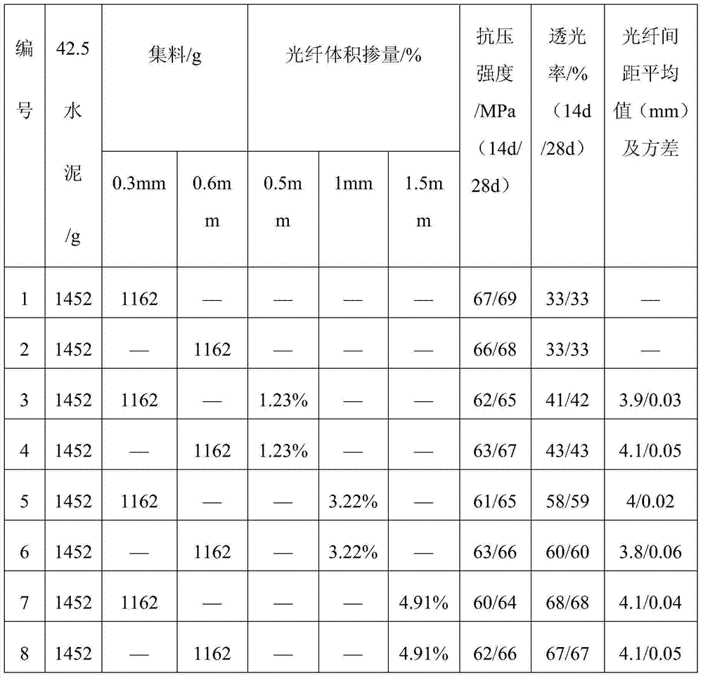
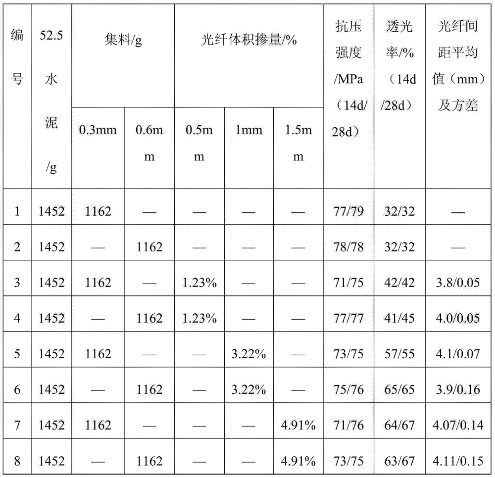
[0033] The raw material composition of mortar in embodiment example 1 and 2 is respectively as follows: In order to reach the cement paste of high fluidity and high strength, select cement to be produced in Tangshan 42.5 quick-hardening sulfoaluminate cement, 3d compressive strength and flexural strength are respectively The cement is 42.9MPa and 8.4MPa and the cement is 52.5 quick-hardening sulfoaluminate cement produced in Tangshan. The 3d compressive strength and flexural strength are 53.9MPa and 10.4MPa respectively; the maximum particle size of the two aggregates selected is not more than 0.3mm and 0.6mm, the prepared mortar has a water-cement ratio of 0.35 and a sand-cement ratio of 0.8. The measured mortar consistency is 16cm and 15cm, and the compressive strength is higher than 60MPa. -8H powder polycarboxylate superplasticizer, the water reducing rate is 30%; the content of defoamer is 0.2%, which is P764 powder defoamer produced by Shenzhen Hairun Chemical Co., Ltd.; ...


PUM

PropertyMeasurementUnit
compressive strengthaaaaaaaaaa
diameteraaaaaaaaaa
strengthaaaaaaaaaa

Abstract

The invention discloses a method for preparing light transmitting concrete through application of optical fiber winding machine technology and belongs to the field of novel building materials. According to the method for preparing light transmitting concrete through application of optical fiber winding machine technology, organic material multimode optical fibers with the diameter from 0.5 mm to 1.5 mm are adopted, the optical fibers are wound to an optical fiber winding machine until an optical fiber integrated body with the preset width is formed to serve as a conductor for transmitting the optical fibers, and the specific effect of light transmitting and image transmission through cement concrete materials is achieved. The light transmitting concrete which is the novel fourth generation light transmitting concrete material has the advantages of being simple in technology and easy to operate, enabling light transmitting performance to be guaranteed and having good application prospect.

Description

technical field [0001] The invention belongs to the technical field of new concrete materials. Specifically, it relates to a preparation method of light-transmitting concrete with high light transmission, high strength, high stability, low cost, simple preparation process and industrialization. Compared with the third-generation light-transmitting cement-based materials, this cement-based material has the advantages of simple preparation process, stable optical fiber positioning effect and light transmission performance, and high strength. There are broad prospects. Background technique [0002] Although there have been related reports on cement-based light-transmitting concrete, there are few reports on the specific preparation process of cement-based light-transmitting materials. Arrange in parallel in the warp or weft direction, fix with cotton yarn, treat the surface of the optical fiber with a coupling agent, fix the fiber in the trial mold with a steel rod and a nail...

Claims


Application Information

Patent Timeline
Patent Type & Authority Applications(China)
IPC IPC(8): B28B1/04
CPCB28B1/008B28B1/045B28B1/42
Inventor 李悦刘雄飞郭慧董万国施同飞谢丹妮李嘉奇
Owner BEIJING UNIV OF TECH
Learn More