
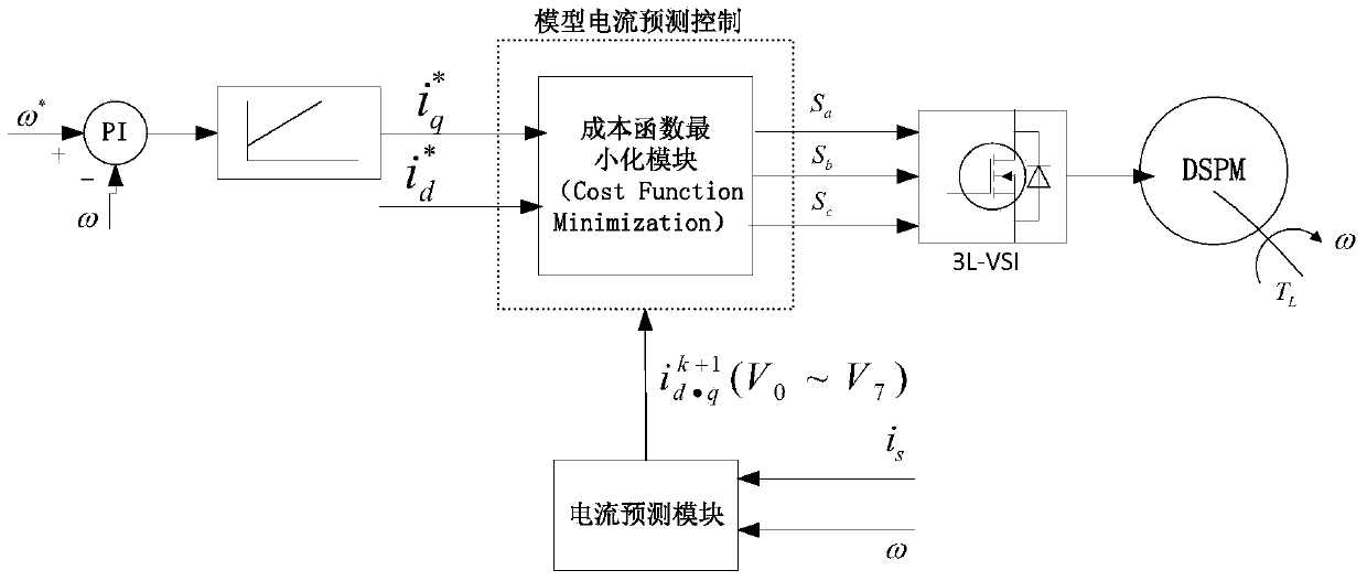
Double salient permanent magnet (DSPM) current control method based on model prediction

A permanent magnet synchronous motor and current control technology, which is applied in the direction of motor generator control, electronic commutation motor control, control system, etc. DSPM driving ability and other issues

Active Publication Date: 2014-04-23
HUAZHONG UNIV OF SCI & TECH
View PDF5 Cites 19 Cited by
  • Summary
  • Abstract
  • Description
  • Claims
  • Application Information

AI Technical Summary

Problems solved by technology

The dynamic response speed of this type of control strategy is slow, and at the same time, the requirements for motor parameters are high, and it is difficult to determine the time and angle of current shutdown during the control process, which seriously affects the driving ability of DSPM
In addition, in practical applications, due to the influence of temperature rise and frequency, the parameters such as inductance and resistance of DSPM will change to a certain extent, coupled with various peripheral signal interference, there will be large errors when selecting the current off time and angle. The torque of the DSPM is further deteriorated, which in turn increases the drive loss of the inverter of the DSPM

Method used


Image

  • Double salient permanent magnet (DSPM) current control method based on model prediction
  • Double salient permanent magnet (DSPM) current control method based on model prediction
  • Double salient permanent magnet (DSPM) current control method based on model prediction

Examples


Embodiment Construction

[0020] In order to make the object, technical solution and advantages of the present invention clearer, the present invention will be further described in detail below in conjunction with the accompanying drawings and embodiments. It should be understood that the specific embodiments described here are only used to explain the present invention, not to limit the present invention. In addition, the technical features involved in the various embodiments of the present invention described below can be combined with each other as long as they do not constitute a conflict with each other.

[0021] The basic mathematical equation of a doubly salient permanent magnet motor is as follows:

[0022] Flux linkage equation:

[0023] ψ A ψ B ψ ...


PUM


Abstract

The invention discloses a double salient permanent magnet (DSPM) current control method, which comprises the following steps: obtaining eight groups of inverter switching vector signal; at the current time k, predicting p-phase stator current of next time k+1 in each group of inverter switching vector signal (img file='DDA0000448969140000011.TIF' wi='88' he='65' / ), wherein p represents A, B and C phases of a motor; in each group of inverter switching vector signal, obtaining the current predicted value of d -axis and q -axis according to (img file='DDA0000448969140000012.TIF' wi='96' he='64' / ); in each group of inverter switching vector signal, calculating d-axis current prediction error (img file='DDA0000448969140000013.TIF' wi='72' he='64' / ) and q-axis current prediction error (img file='DDA0000448969140000014.TIF' wi='104' he ='68' / ) of the next time k +1; according to (img file='DDA0000448969140000015.TIF' wi='72' he ='66' / ) and (img file='DDA0000448969140000016.TIF' wi='112' he='64' / ), selecting the switching vector signal of the minimum total amount of torque fluctuation and flux fluctuation as a drive signal of the inverter switch, thereby real-time controlling on-off of a inverter switch tube. The method by accurately controlling the DSPM motor output current, accurately control the inverter switching vector change, so that the motor torque fluctuation and flux fluctuation are minimum, the requirement for electrode parameters is low, and the response speed is fast.

Description

technical field [0001] The invention belongs to the technical field of doubly salient pole permanent magnet synchronous motors, and more specifically relates to a current control method of doubly salient pole permanent magnet synchronous motors based on model prediction. Background technique [0002] The basic structure of Doubly Salient Permanent Magnet Synchronous Machine (DSPM) was first proposed by Rauch and Johnson in the 1950s. Due to the limitations of power electronics and motor control technology at that time, it failed to attract attention in the industry. . In the early 1990s, Professor T.A.Lipo of the University of Wisconsin-Madison in the United States conducted a comprehensive and in-depth study on the new structure and electromagnetic model of DSPM. Related theoretical and experimental studies showed that DSPM has strong mechanical robustness and high Moment density, which has gradually aroused the research interest of international colleagues (R.F.Schiferl a...

Claims


Application Information

Patent Timeline
IPC IPC(8): H02P21/12
Inventor 徐伟
Owner HUAZHONG UNIV OF SCI & TECH
Learn More