
Compound technology for metallization of front side of solar cell

A solar cell and composite process technology, which is applied in the composite process field of solar cell front metallization, can solve problems such as limitations, and achieve the effect of improving product quality and production efficiency

Inactive Publication Date: 2014-04-23
HANGZHOU SILARS TECH
View PDF4 Cites 2 Cited by
  • Summary
  • Abstract
  • Description
  • Claims
  • Application Information

AI Technical Summary

Problems solved by technology

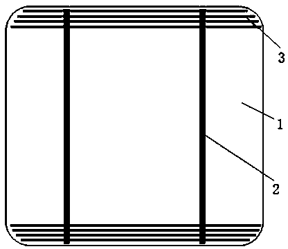
For polycrystalline silicon solar cells, due to its regular rectangular shape, it is very convenient to apply WEM technology to make all the fine grid lines; but for monocrystalline silicon solar cells, the length of the fine grid line paste at the chamfered parts are different from the paste length of the fine grid lines in the central rectangular part, which limits the application of efficient WEM technology on monocrystalline silicon solar cells with arc-shaped chamfers

Method used


Image

  • Compound technology for metallization of front side of solar cell
  • Compound technology for metallization of front side of solar cell
  • Compound technology for metallization of front side of solar cell

Examples


Embodiment 1

[0027] In this embodiment, the production of polysilicon solar cells is taken as an example, and the steps of the composite process of metallizing the front side of the cell are as follows:

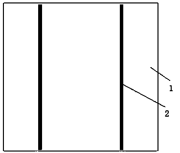
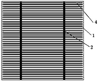
[0028] 1. Design a printing screen with only busbars, and prepare busbars 2 on the polysilicon solar cell 1 by screen printing technology. The width of the busbars is 1.5mm, a total of 2, evenly distributed on the surface of the cell;

[0029] 2. Use WEM technology to prepare thin grid lines 4 in the direction perpendicular to the main grid line 2: select 80 metal wires with a diameter range of 0.01mm-0.03mm as conductive wires, and arrange 80 conductive wires in parallel at equal intervals to conduct electricity. The spacing between the wires is 0.5mm-3mm; then the surface of the conductive wires is uniformly coated with a layer of conductive paste by a coating mechanism; the conductive wires coated with the conductive paste are adhered to On the battery sheet, the thin grid line 4 on th...

Embodiment 2

[0034] In this embodiment, the production of monocrystalline silicon solar cells is taken as an example, and the steps of the composite process of metallizing the front of the cell are as follows:

[0035] 1. Design a printing screen with busbars and thin gridlines at the rounded corners, and prepare busbars 2 with a width of 1.5mm on the monocrystalline silicon solar cell 1 by screen printing technology, a total of 2 pieces , and at the same time, use screen printing technology to prepare thin grid lines 3 in the arc-shaped chamfering area of ​​the edge of the battery sheet, 4 on each side, and the closest thin grid line 3 is 1.5mm away from the edge of the battery sheet;

[0036] 2. Use WEM technology to prepare thin grid lines 4 in the direction perpendicular to the main grid line 2: select 60 metal wires with a diameter range of 0.01mm-0.03mm as conductive wires, and arrange 60 conductive wires in parallel at equal intervals to conduct electricity. The spacing between the ...


PUM


Abstract

The invention relates to the field of preparation technology of solar cells, and specifically relates to a compound technology for metallization of the front side of a solar cell. Main grid lines of the solar cell or main grind lines and partial fine grid lines of the solar cell are prepared by taking a traditional technology as basic technology, and fine grid lines of the front side of the solar cell are prepared by taking an emerging wire enhanced metallization (WEM) technology as main technology, so that the flexibility when a traditional metallization technology is used is fully showed, and the characteristic of high efficiency of the WEM technology is also showed; therefore, the limits of existing equipment for the WEM technology in comprehensive application of solar cell production are broken through.

Description

technical field [0001] The invention relates to the field of solar cell preparation technology, in particular to a composite process for front metallization of solar cells. Background technique [0002] Crystalline silicon solar cells include monocrystalline silicon solar cells and polycrystalline silicon solar cells. Generally speaking, polycrystalline silicon solar cells are mainly based on a rectangular silicon wafer with regular shape, while monocrystalline silicon solar cells are mainly based on a circular shape. Chamfered quasi-rectangular silicon wafer. [0003] The traditional front electrode of the solar cell is mainly printed by the screen printing process to make the front electrode of the solar cell. Since the required printing pattern can be designed on the screen at one time, the traditional screen printing process can complete the front electrode of the solar cell at one time. For the preparation of bus bars and fine grid lines, this front metallization proce...

Claims


Application Information

Patent Timeline
Patent Type & Authority Applications(China)
IPC IPC(8): H01L31/18H01L31/0224
CPCH01L31/022425Y02E10/50Y02P70/50
Inventor 武宇涛秋晨阙文修
Owner HANGZHOU SILARS TECH
Learn More