An ion measuring device
A measuring device and ion technology, which is applied to the parts of the particle separator tube, sample introduction/extraction, etc., can solve the problems of unmaintainable and purposeful detection of ion transmission efficiency, etc., to achieve small measurement errors and improve reliability performance and maintainability, ease of measurement
- Summary
- Abstract
- Description
- Claims
- Application Information
AI Technical Summary
Problems solved by technology
Method used
Image

Examples
Embodiment 1
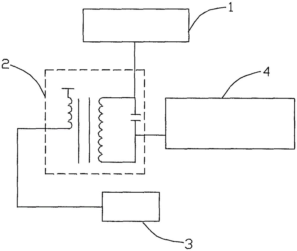
[0031] see figure 1 , a kind of ion measurement device, comprises ion optics system 1, isolated pulse power supply 2, control unit 3 and processing unit 4; Described ion optics system 1 comprises ion lens; Described control unit 3 and processing unit 4 and described isolation pulse connected to the power supply;
[0032] The control unit 3 controls the isolated pulse power supply 2 to provide voltage to the ion lens, ions impact on the ion lens to form an ion current, and the ion current is output from the relative ground terminal of the secondary side of the pulse isolation power supply;
[0033] The ion current output from the opposite ground terminal of the pulse isolation power supply 2 is received by the processing unit 4 and calculated by the processing unit 4 to obtain the corresponding ion transmission quantity. Preferably, the control unit 3 can obtain the corresponding ion transmission efficiency according to the ion transmission quantity.
[0034] Preferably, the ...
Embodiment 2
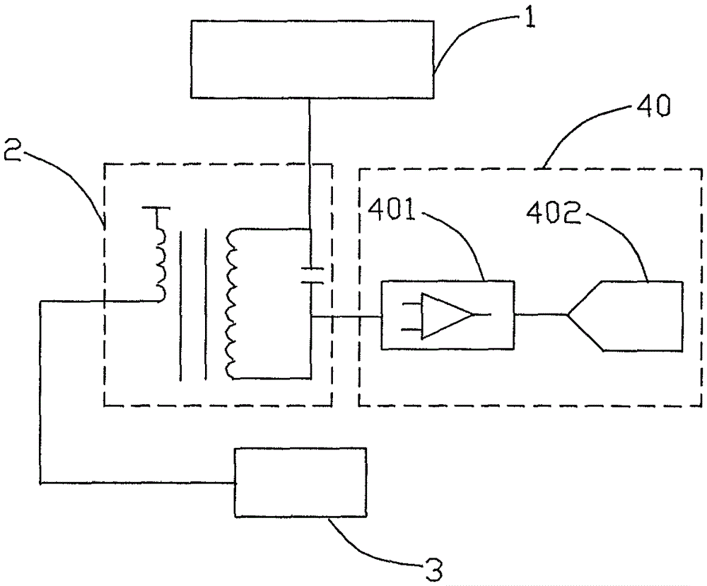
[0037] see figure 2 , a kind of ion measuring device, different from the ion measuring device described in embodiment 1 is:
[0038] The processing unit 40 includes an operational amplifier circuit 401 and an analog-to-digital converter 402 , and the opposite ground terminal of the secondary side of the isolated pulse power supply 2 is connected to the input terminal of the operational amplifier circuit 401 .
[0039] Preferably, the operational amplifier circuit includes a logarithmic amplifier circuit.
[0040] The analog-to-digital converter 402 in this embodiment is a 24-bit ADC processor.
[0041] Since the input terminal of the operational amplifier circuit is at the same potential as the ground terminal, the relative ground terminal of the secondary side of the isolated pulse power supply is connected to the input terminal of the operational amplifier circuit, which is equivalent to realizing the relative ground terminal of the secondary side of the isolated pulse pow...
Embodiment 3
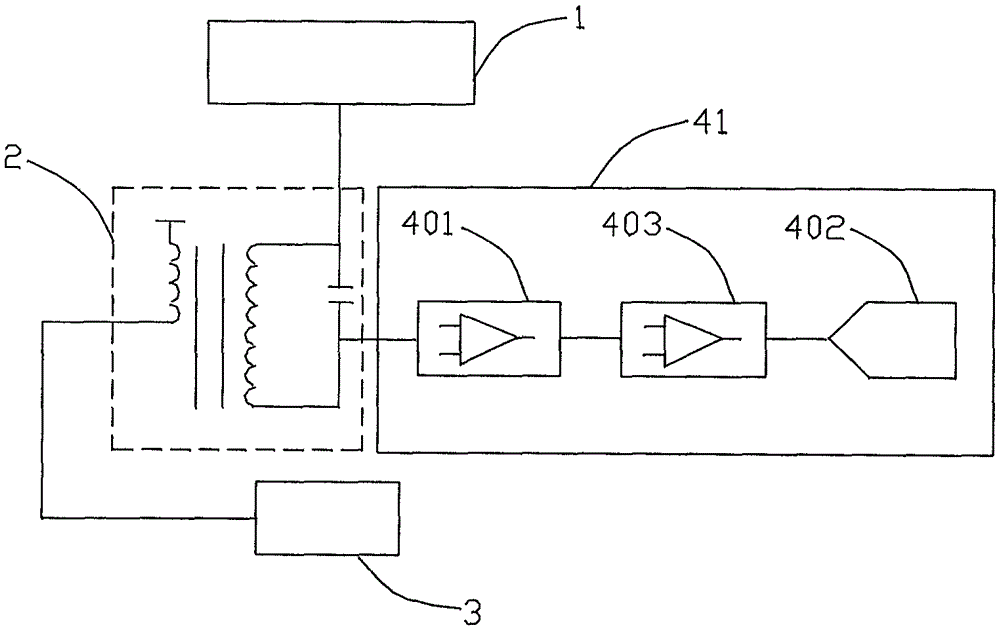
[0045] see image 3 , a kind of ion measuring device, different from the ion measuring device described in embodiment 2 is
[0046] The processing unit 41 also includes a filtering circuit 403 . The filter circuit is placed between the operational amplifier circuit 401 and the analog-to-digital converter 402 . In order to prevent the interference of the external leakage current, the signal input line of the filter circuit 403 is double shielded and directly connected to the input pin of the operational amplifier circuit.
[0047] In the case that the radio frequency voltage amplitude is high, thereby causing radiation interference or conduction interference to the circuit, the ion measurement device can effectively remove the interference of the radio frequency power supply inside the vacuum cavity in the ion optical system, and at the same time prevent the interference of external leakage current, so that the ion The measuring device has strong anti-interference ability.
PUM
 Abstract
Description
Claims
Application Information
 - R&D
- Intellectual Property
- Life Sciences
- Materials
- Tech Scout
- Unparalleled Data Quality
- Higher Quality Content
- 60% Fewer Hallucinations
Browse by: Latest US Patents, China's latest patents, Technical Efficacy Thesaurus, Application Domain, Technology Topic, Popular Technical Reports.
© 2025 PatSnap. All rights reserved.Legal|Privacy policy|Modern Slavery Act Transparency Statement|Sitemap|About US| Contact US: help@patsnap.com