
Device capable of replacing valve under pressure

A technology for replacing valves and valves, applied in valve devices, pipes/pipe joints/fittings, engine components, etc., can solve problems such as valve plate erosion, seal corrosion, energy consumption, etc., to achieve reliable engagement and disengagement, guaranteeing Operation and control, the effect of ensuring seal quality

Active Publication Date: 2014-04-23
袁占良
View PDF4 Cites 6 Cited by
  • Summary
  • Abstract
  • Description
  • Claims
  • Application Information

AI Technical Summary

Problems solved by technology

Due to the long-term exposure to the very harsh environment in the field and the erosion of acid and alkali water media all the year round, and little maintenance, after the equipment has been in operation for a long time, the valve will have erosion of the valve plate, aging and corrosion of the seals, etc., which seriously affect its use. Functional phenomena, resulting in difficulty in opening or closing these valves, corrosion of seals, leakage and other problems, bringing great trouble to workover and oil field production, these valves need to be replaced to restore the normal function of the equipment
Since the valves on this type of equipment are operating under high pressure, one way to replace these valves is to rely on the natural infiltration of the formation to reduce the pressure after the shutdown, and replace them in a non-pressurized state. The shutdown time generally takes more than ten days Even for a month, it will seriously affect the production of the oilfield and restore the formation pressure, which will consume a lot of water and electricity resources, and such an approach will be detrimental to the production of the enterprise. The formation pressure established by water injection will be destroyed, which will seriously affect the subsequent production of the enterprise, resulting in huge production loss and energy consumption
Another way is to carry out operation maintenance. It needs to use huge operation equipment such as operation derrick and workover truck to carry out the maintenance under pressure. It usually takes 2-3 days to complete and requires high operation costs.

Method used


Image

  • Device capable of replacing valve under pressure
  • Device capable of replacing valve under pressure
  • Device capable of replacing valve under pressure

Examples


Embodiment Construction

[0039] In order to make the object, technical solution and advantages of the present invention more clear, the present invention will be further described in detail below in conjunction with the accompanying drawings and embodiments. It should be understood that the specific embodiments described here are only used to explain the present invention, not to limit the present invention.

[0040] The existing pipeline pressure change valve technology is to send the special plugging tool to the predetermined position, and rely on external force (screw rotation) to drive the seat seal of the expansion part, which cannot control the expansion force and the clamping state of the slips. During the construction process It is very easy for the slips to slip and the occluder to come out, resulting in vicious accidents such as injury or loss of control due to high-pressure liquid (gas) eruption, posing a very large safety hazard.

[0041] The invention adopts a very scientific and reasonab...


PUM


Abstract

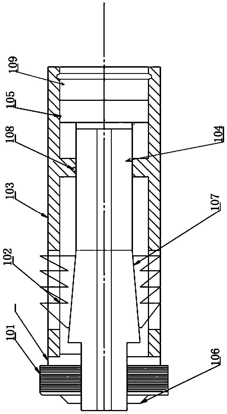
The invention provides a device capable of replacing a valve under pressure. The device comprises a plugging device, a combining part, a blowout prevention pipe, a hydraulic cylinder, a piston rod and an operating rod. One end of the combining part is detachably connected to the plugging device, and the blowout prevention pipe contains the plugging device and the combining part and is connected with the hydraulic cylinder. The plugging device is mainly composed of a sealing rubber sleeve, a slip bowl seal assembly, a differential pressure type piston and slips, the slips can be automatically unfolded through fluid pressure, and thus safe bowl seal is achieved. One end of the combining part is connected with the hydraulic cylinder through the piston rod and the operating rod which penetrate through the blowout prevention pipe. The invention further provides a method for replacing a valve under pressure with the device capable of replacing a valve under pressure. The device achieves seal, bowl seal, seal removal and internal pressure balance of a tool, the complex functions can be continuously and automatically completed in one travel, and thus the device is easier and more reliable to operate. Uncertainty caused by manual operation is reduced, safety in the construction process is guaranteed, no pollution will be caused to the environment, and construction cost is greatly reduced.

Description

technical field [0001] The invention relates to a pressure replacement device for valve replacement and maintenance, in particular to the replacement and maintenance of valves under pressure for oil production wellheads, high-pressure water injection wellheads, high-pressure manifolds and the like. Background technique [0002] Oil production wellheads, water injection wellheads, and manifolds are important basic equipment in modern petroleum production engineering, and high-pressure valves are the main components of such equipment. Due to the long-term exposure to the very harsh environment in the field and the erosion of acid and alkali water media all the year round, and little maintenance, after the equipment has been in operation for a long time, the valve will have erosion of the valve plate, aging and corrosion of the seals, etc., which seriously affect its use. The phenomenon of function causes these valves to be difficult to open or close, the seals are corroded, le...

Claims


Application Information

Patent Timeline
Patent Type & Authority Applications(China)
IPC IPC(8): F16K43/00
CPCF16L55/1283
Inventor 袁占良郭煜姜兆洪袁玉良
Owner 袁占良
Learn More