
Semiconductor device manufacturing method

A device manufacturing method and semiconductor technology, applied in semiconductor/solid-state device manufacturing, semiconductor devices, electrical components, etc., can solve problems such as device performance degradation, DSL integration failure, etc., and achieve the effect of process integration

Active Publication Date: 2017-09-26
SOI MICRO CO LTD
View PDF4 Cites 0 Cited by
  • Summary
  • Abstract
  • Description
  • Claims
  • Application Information

AI Technical Summary

Problems solved by technology

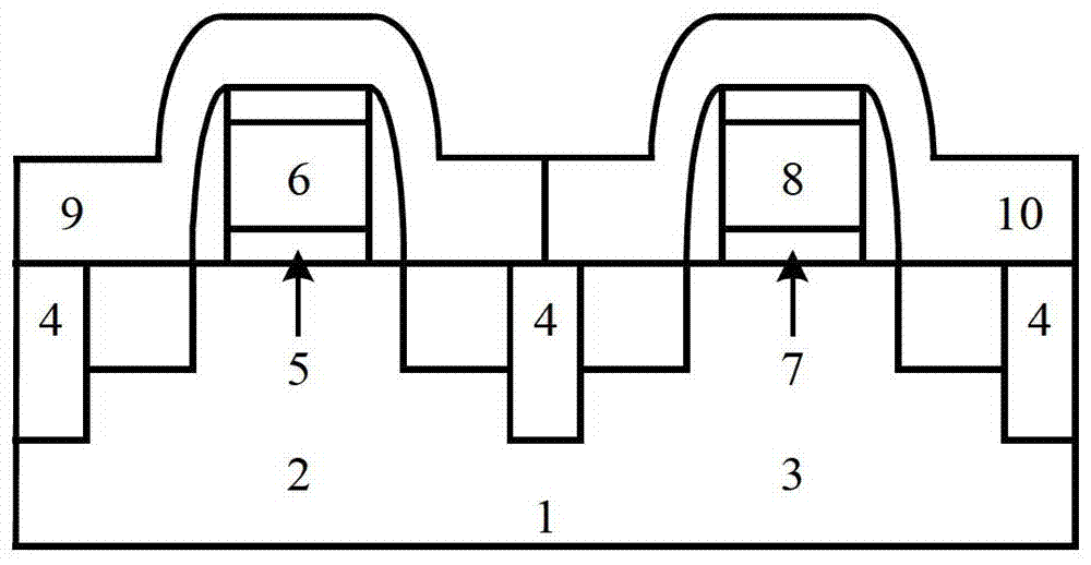
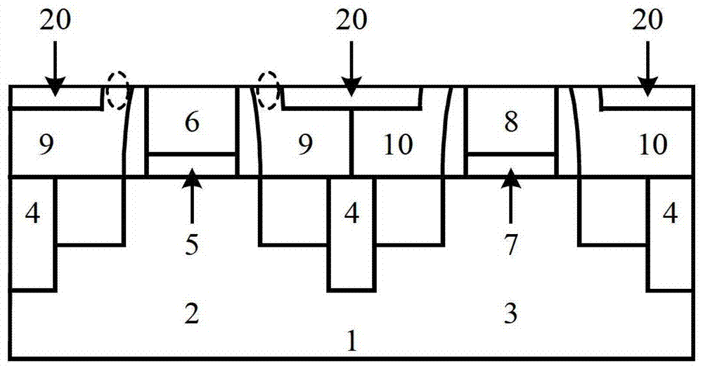
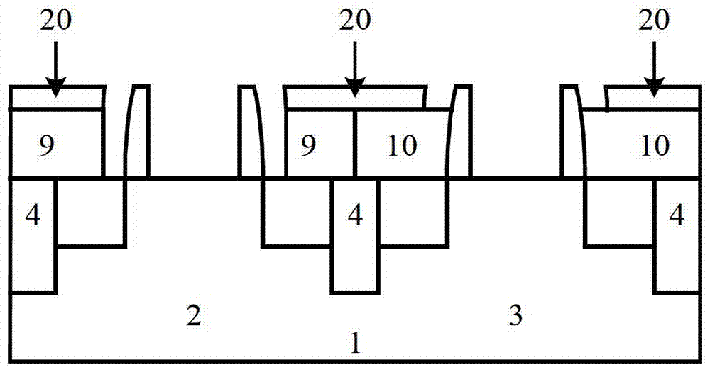
The current method is to deposit the TEOS layer 20 after forming the stress layer, and then perform CMP to open the dummy gate, see the attached figure 2 , and then remove the dummy gate and the dummy gate insulating layer. However, the problem faced by this method is that the dummy gate insulating layer is usually silicon oxide, and the removal method is DHF wet etching. Specifically, at room temperature (23 degrees Celsius), the 1:100 DHF corrosion rate of silicon oxide is 30±1 angstroms / min, but at the same time, the etching rate of tensile stress silicon nitride in DHF under this condition is 498 angstroms / min, which is much higher than The corrosion rate of silicon oxide in DHF, because a part of tensile stress layer 9 will be exposed after CMP and not covered by TEOS layer 20, see figure 2 The position shown by the dotted circle in the middle, in this way, when the dummy gate insulating layer is removed, the exposed tensile stress layer 9 is corroded to form holes, see the attached image 3 If this problem is not solved, it will lead to the filling of high-k material and metal gate material into the hole in the subsequent high-k metal gate process, resulting in the degradation of device performance. At the same time, due to the loss of the stress layer, DSL integration will fail.

Method used


Image

  • Semiconductor device manufacturing method
  • Semiconductor device manufacturing method
  • Semiconductor device manufacturing method

Examples


Embodiment Construction

[0028] Hereinafter, the present invention is described by means of specific embodiments shown in the drawings. It should be understood, however, that these descriptions are exemplary only and are not intended to limit the scope of the present invention. Also, in the following description, descriptions of well-known structures and techniques are omitted to avoid unnecessarily obscuring the concept of the present invention.

[0029] The present invention provides a method for manufacturing a semiconductor device, and in particular relates to a method for manufacturing a transistor using spacer technology. Please refer to the attached Figure 4-9 , the semiconductor device manufacturing method provided by the present invention will be described in detail.

[0030] First, see attached Figure 4 , on the semiconductor substrate 1 , NMOS 2 and PMOS 3 are formed, and different MOS transistors are isolated by STI structures 4 . Wherein, in this embodiment, a single crystal silicon ...


PUM


Abstract

The invention provides a stress semiconductor manufacturing method. In the stress semiconductor manufacturing method, a tensile stress layer is formed in an NMOS region so as to form a pressure stress layer in a PMOS, TEOS deposits and planarization treatment is performed, and then a protective layer deposits wholly. A gate electrode line mask is adopted to perform photoetching and etching on the protective layer, and a dummy gate electrode is opened. Due to the fact that the protective layer completely covers the tensile stress layer and the pressure stress layer and the corrosion rate of the protective layer in a wet etching solution is very low, the tensile stress layer and the pressure stress layer are not damaged, and the defects in the prior art are overcome. In addition, manufacture of high K gate insulating layer and a metal gate electrode are finished after a gate electrode groove is formed, and integration of a gate-last process and a double-strain stress layer process is achieved.

Description

technical field [0001] The invention relates to the field of manufacturing methods of semiconductor devices, in particular to an integration method of a double strain stress layer applied in a CMOS gate-last process. Background technique [0002] After semiconductor integrated circuit technology enters the technology node of 90nm feature size, it becomes more and more challenging to maintain or improve transistor performance. After the 90nm node, stress technology is gradually adopted to improve device performance. At the same time, in terms of manufacturing process, the high-K metal gate technology in the gate last process (gate last) is also gradually adopted to meet the challenges brought about by the continuous reduction of devices. In the stress technology, the dual stress layer (DSL, dual stress liner) technology has high compatibility with conventional processes and low cost, so it is adopted by major semiconductor manufacturers. [0003] DSL technology refers to th...

Claims


Application Information

Patent Timeline
Patent Type & Authority Patents(China)
IPC IPC(8): H01L21/8238H01L21/28
CPCH01L21/823828H01L29/66545H01L29/7843
Inventor 秦长亮尹海洲殷华湘
Owner SOI MICRO CO LTD
Learn More