
A fully shielded high voltage isolated voltage transformer

A voltage transformer, high-voltage isolation technology, applied in the direction of inductors, transformer/inductor housing, voltage/current isolation, etc., can solve the problems affecting the voltage transformer error, imperfect shielding, etc., to improve accuracy and compact structure , the effect of uniform distribution of the electric field in space

Active Publication Date: 2016-04-20
STATE GRID CORP OF CHINA +2
View PDF5 Cites 0 Cited by
  • Summary
  • Abstract
  • Description
  • Claims
  • Application Information

AI Technical Summary

Problems solved by technology

[0002] In my country's power frequency voltage value traceability system, the series addition of voltage transformers is used to trace the value of the voltage ratio. This method directly connects the primary and secondary shielding electrodes of two voltage transformers in series during the operation process. When the potential of each shielding layer changes during the process, it will not affect the error of the voltage transformer; but in fact, due to the imperfect shielding, when the shielding potential changes, the leakage current flows through the excitation winding, which affects the error of the voltage transformer , with the increase of voltage level, the influence of capacitive leakage becomes more obvious
[0003] Judging from the current research, it is difficult for standard devices above 220kV voltage level to use voltage series addition to transfer values. Therefore, in order to use voltage series addition to transfer values ​​to higher voltage levels, it is necessary to solve the voltage transformer The problem of secondary voltage series connection, while reducing the impact of the capacitive leakage of the primary and secondary windings on the measurement error

Method used


Image

  • A fully shielded high voltage isolated voltage transformer
  • A fully shielded high voltage isolated voltage transformer
  • A fully shielded high voltage isolated voltage transformer

Examples


Embodiment Construction

[0043] In order to better understand the present invention, the content of the present invention will be further explained below in conjunction with the accompanying drawings.

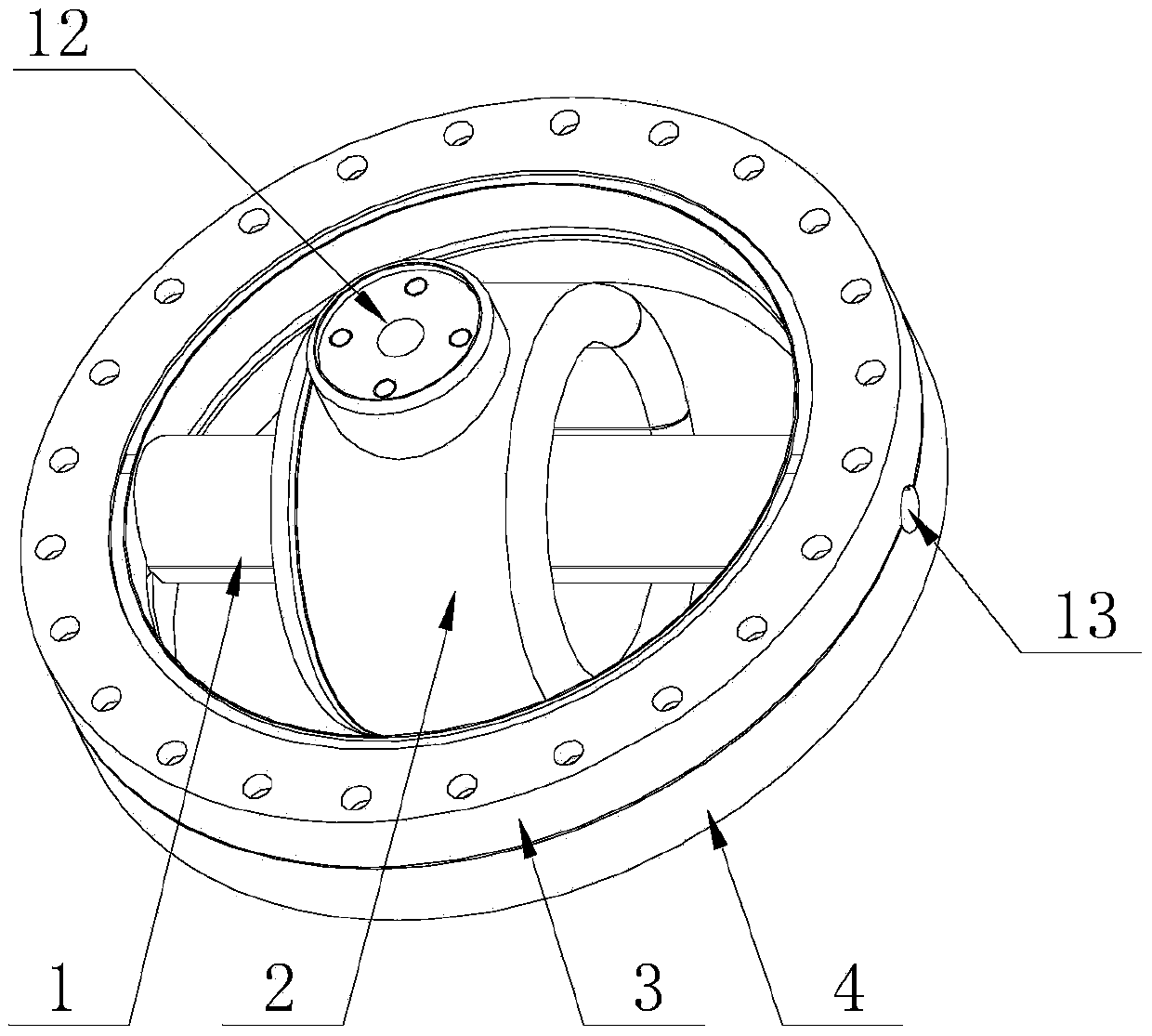
[0044] like figure 1 Shown:

[0045] The invention provides a fully shielded high-voltage isolated voltage transformer, which is characterized in that:

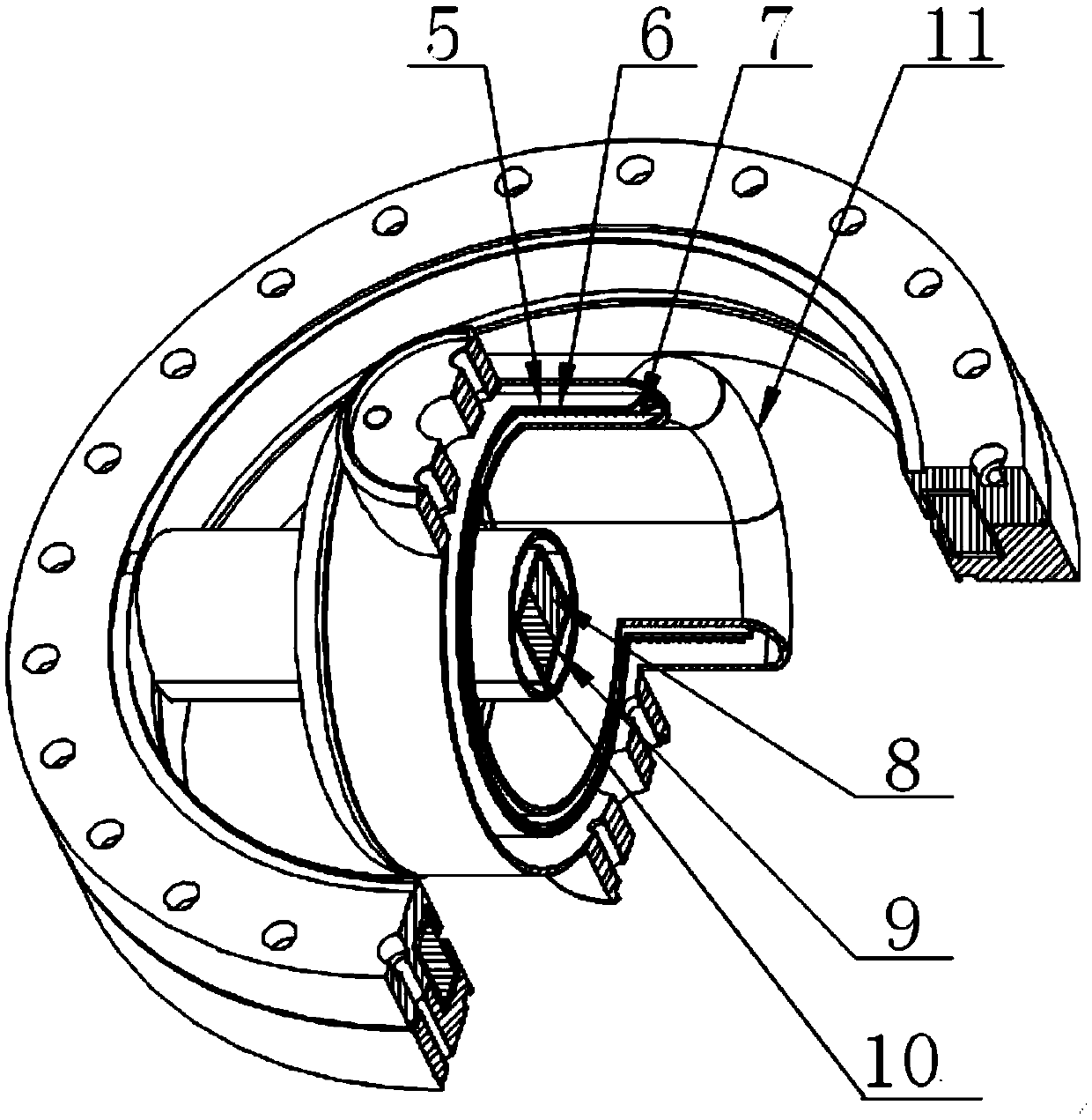
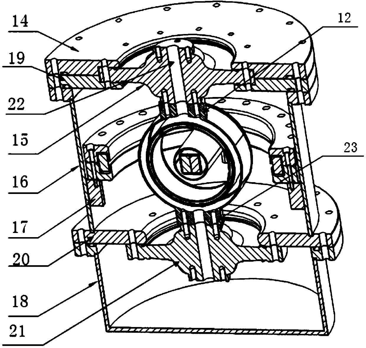
[0046] The voltage transformer includes a tubular secondary low-voltage shielding electrode (1) coaxially installed in the ring-shaped primary high-voltage shielding electrode (2), flanges for respectively fixing the primary high-voltage shielding electrode (2) and the secondary low-voltage shielding electrode (1) ;

[0047] The flange (12) and the flange (23) for fixing the primary high-voltage shielding electrode (2) are arranged in parallel on the outer side of the primary high-voltage shielding electrode (2);

[0048] The axes of the flange (3) and the flange (4) that fix the secondary low-voltage shielding electrode (1) are perpendicular to the ...


PUM

PropertyMeasurementUnit
diameteraaaaaaaaaa
diameteraaaaaaaaaa

Abstract

A full-shielding high-voltage isolated-type voltage transformer comprises a tubular secondary low-voltage shielding electrode (1) coaxially mounted in an annular primary high-voltage shielding electrode (2), and flanges fixing the primary high-voltage shielding electrode and the secondary low-voltage shielding electrode respectively. A flange (12) and a flange (23) which fix the primary high-voltage shielding electrode are disposed on the outer side of the primary high-voltage shielding electrode in parallel, axes of a flange (3) and a flange (4) which fix the secondary low-voltage shielding electrode are perpendicularly intersected at the axis of the secondary low-voltage shielding electrode, and both the primary high-voltage shielding electrode and the secondary low-voltage shielding electrode are made of aluminum alloy. For the full-shielding high-voltage isolated-type voltage transformer, accuracy of a voltage transformer is improved, secondary voltages can be superimposed when two single-stage voltage transformers are serially connected, and a voltage series summation method is promoted to perform quantity transmission on higher voltage levels.

Description

Technical field: [0001] The invention relates to a transformer, in particular to a fully shielded high-voltage isolated voltage transformer, which belongs to the technical field of instrument voltage transformers. Background technique: [0002] In my country's power frequency voltage value traceability system, the series addition of voltage transformers is used to trace the value of the voltage ratio. This method directly connects the primary and secondary shielding electrodes of two voltage transformers in series during the operation process. When the potential of each shielding layer changes during the process, it will not affect the error of the voltage transformer; but in fact, due to the imperfect shielding, when the shielding potential changes, the leakage current flows through the excitation winding, which affects the error of the voltage transformer , as the voltage level increases, the impact of capacitive leakage becomes more pronounced. [0003] Judging from the cu...

Claims


Application Information

Patent Timeline
Patent Type & Authority Patents(China)
IPC IPC(8): H01F38/26H01F27/29H01F27/30H01F27/02H01F27/32H01F27/28G01R15/18
CPCH01F38/26H01F27/2885
Inventor 周峰袁建平姜春阳殷小东周利华
Owner STATE GRID CORP OF CHINA
Learn More