
Inflatable loading positioning device and loading positioning method of columns

A positioning device, an inflatable technology, applied in the direction of measuring devices, using stable tension/pressure testing material strength, instruments, etc., can solve problems such as easy to dump and difficult to move

Inactive Publication Date: 2014-04-16
ZHEJIANG COLLEGE OF CONSTR
View PDF5 Cites 9 Cited by
  • Summary
  • Abstract
  • Description
  • Claims
  • Application Information

AI Technical Summary

Problems solved by technology

[0004] Aiming at the defects in the prior art that it is impossible to quickly align the preset loading position, requires a lot of labor, is difficult to move, and is easy to dump, the problem to be solved by the present invention is to provide a one-time, fast, accurate and stable alignment to any preset loading position. The loading positioning device at the loading position (a line or a point), the loading positioning device can not only move freely horizontally, but also vertically lift freely, which can meet the loading requirements of compression columns of different sizes and structures, which is particularly important The most important thing is that it can ensure that the pressure column remains vertically stable during the positioning process, and avoids the pressure column from toppling during the positioning process.

Method used


Image

  • Inflatable loading positioning device and loading positioning method of columns
  • Inflatable loading positioning device and loading positioning method of columns
  • Inflatable loading positioning device and loading positioning method of columns

Examples


Embodiment 1

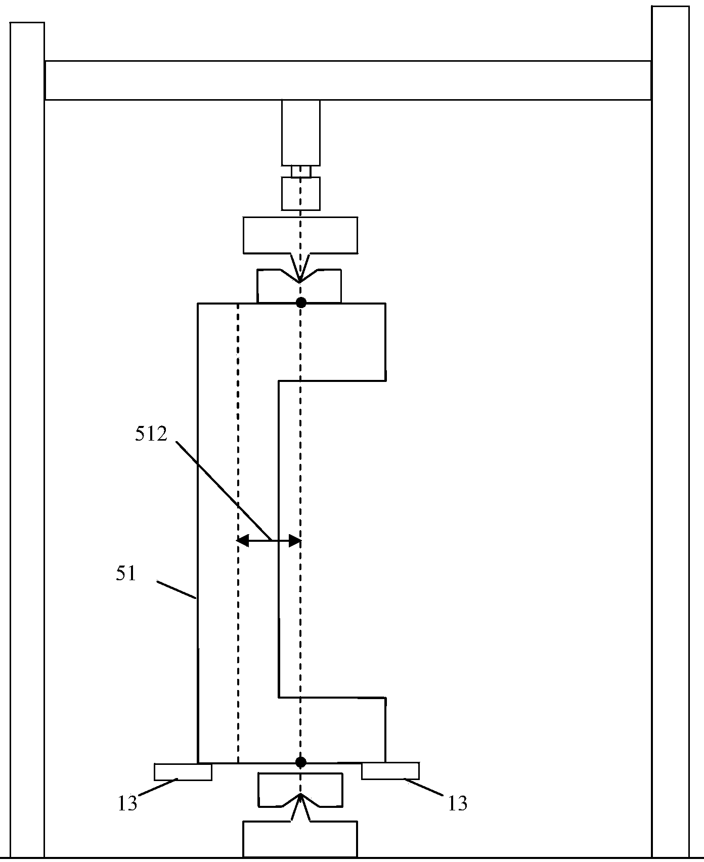
[0070] Embodiment 1: a loading test (see Figure 8 )

[0071] (1) A group of 4 reinforced concrete columns 51 with a cross-sectional size of 200×200mm, a height of 2200mm, and eccentricities 512 (the distance from the load acting position to the axis of the compressed column) are 0 mm, 20 mm, 40 mm, and 100 mm respectively. mm, C30 concrete, the main reinforcement of the column is 4 20, the stirrup is 6150, the protective layer is 15 mm, and the bearing capacity test is carried out on the column 51. The loading position of the column is the eccentricity 512, namely: 0 mm (at the axis), 20 mm, 40 mm, and 100 mm.

[0072] (2) Place the column 51 with an eccentricity of 100 mm to be subjected to the compression test on the positioning auxiliary frame;

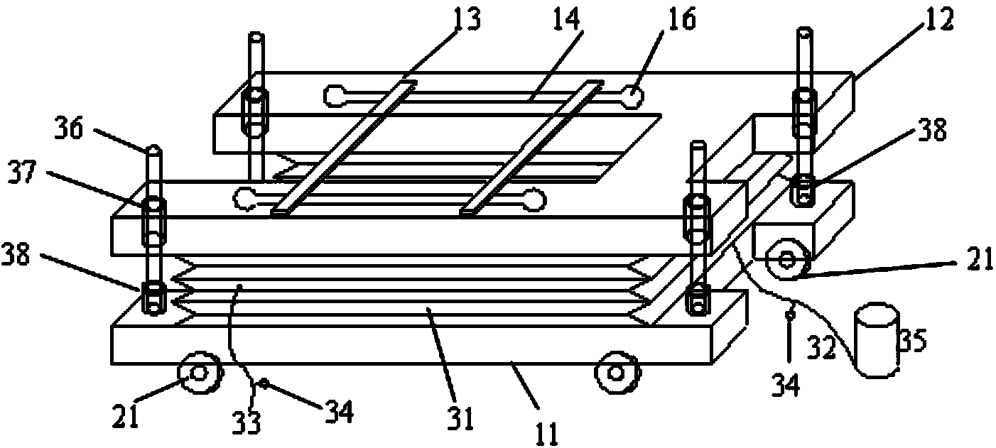
[0073] (3) Close the check valve on the air release pipe 33, inflate the inflator 35, and the air bag 31 rises to drive the "work" type upper floor 12 to move vertically upward along the vertical guide rod 36. When the suspen...

Embodiment 2

[0082] Embodiment 2: secondary loading test (see Figure 9 )

[0083] (1) Carry out residual bearing capacity test on column 51 under the coupled action of load and environment: the cross-sectional size of reinforced concrete column 51 is 120×120mm, the height is 750mm, and the main reinforcement of column 51 is 4 10, the stirrup is 650-100, the protective layer is 15 mm, the length of the protruding column of the flange is 120 mm, the eccentricity 512 is 100 mm, the diameter of the reserved hole 52 is 32 mm, the calculated ultimate bearing capacity of the column 51 is 64kN, and the diameter of the tension bar 53 is 25mm stainless finish rolling thread, the backing plate 54 has a diameter of 100mm and a thickness of 120mm, and the material is steel, and the diameter of the anchor bolt 55 is 55mm. The service load of kN, and the column 51 is placed in the artificial environment simulation box for 365 days to simulate the actual working state of the structure;

[0084] (2) ...


PUM


Abstract

The invention relates to the field of structural tests, particularly a loading positioning device for compressed column tests in civil engineering, which is especially suitable for secondary loading of compressed columns under the coupled actions of load and environment. The loading positioning device comprises a vertical elevation system, a positioning auxiliary frame and a horizontal movement and fixation system, wherein the vertical elevation system is composed of an I-shaped lower bottom plate, an I-shaped upper bottom plate, an airbag with a single-side notch, an inflation tube, an eduction tube, a check valve, an inflation cylinder, a vertical guide rod, a vertical guide sleeve and a stopper. The loading positioning device can quickly, accurately and stably aim at any preset loading position at one time; and the loading positioning device can horizontally and vertically move freely to satisfy the loading demands of compressed columns in different sizes and different structures, and ensure the compressed columns to be always vertical and stable in the positioning process.

Description

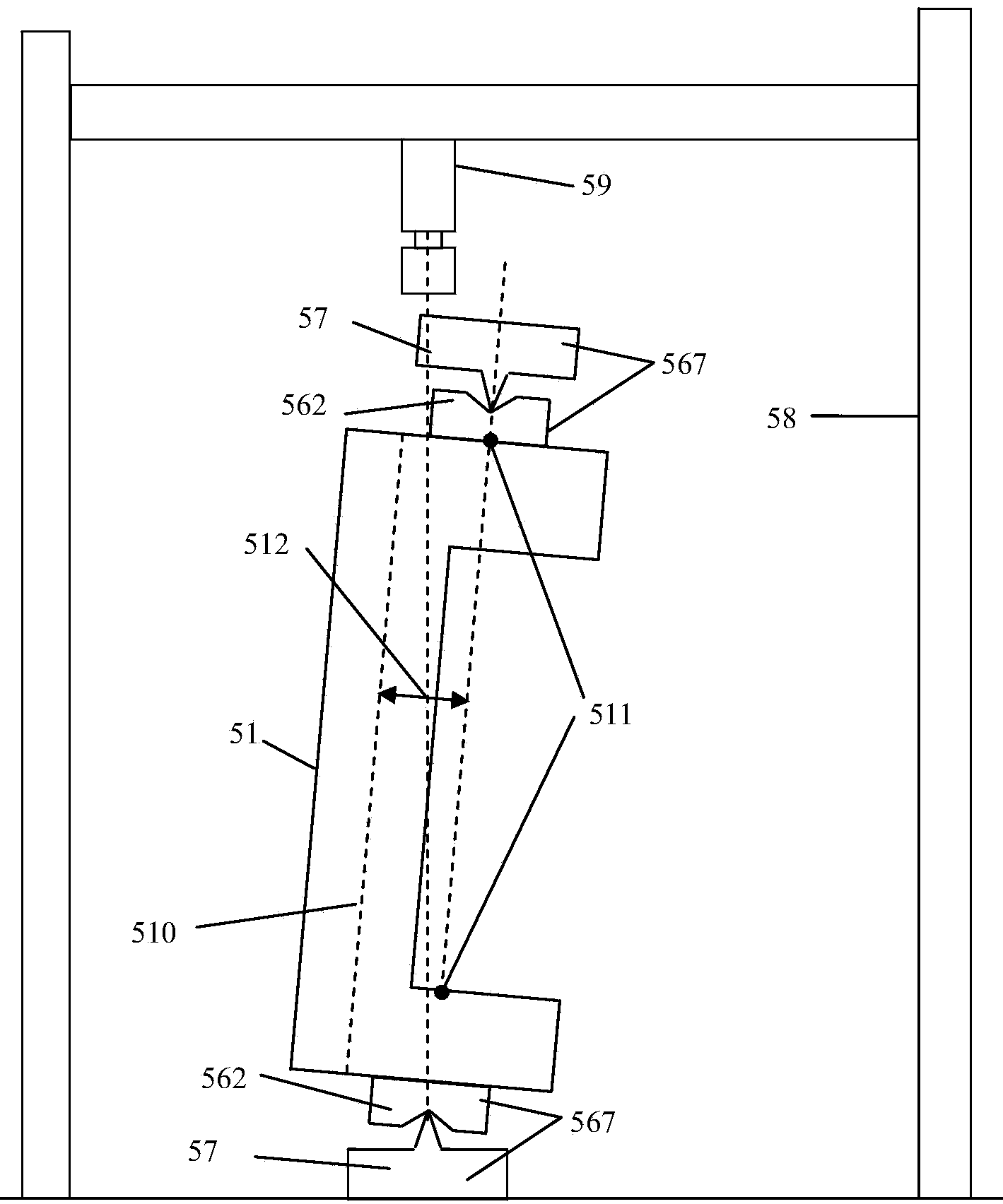
technical field [0001] The invention relates to the field of civil engineering structure tests, in particular to a loading positioning device and a loading positioning method for a compression column test in civil engineering, and is particularly suitable for secondary loading of a compression column under the coupled action of load and environment. Background technique [0002] In civil engineering structural tests, static compression loading tests are often carried out on steel columns, reinforced concrete columns and steel tube concrete columns. In order to accurately simulate the constraint conditions at the end of the specimen and ensure the accuracy of the loading position, knife-strand or ball-strand bearings are often used. Since the knife-strand or ball-strand supports are in line or point contact, they are unstable (such as figure 1 Shown), when the test is in place, the column must be supported by someone to ensure that the column is vertical and does not fall ove...

Claims


Application Information

Patent Timeline
IPC IPC(8): G01N3/08G01N3/02
Inventor 李强童晶蒋学
Owner ZHEJIANG COLLEGE OF CONSTR
Learn More