
Spiral duct machine support frame

A technology of spiral air duct and support frame, which is applied in the field of support frame devices, and can solve problems such as lack of vertical and horizontal movement adjustability

Inactive Publication Date: 2014-04-16
江苏启星新型材料科技有限公司 +1
View PDF0 Cites 2 Cited by
  • Summary
  • Abstract
  • Description
  • Claims
  • Application Information

AI Technical Summary

Problems solved by technology

The support frame of the spiral duct machine produced in the past does not have the function of vertical and horizontal movement adjustability and automatic cutting of the spiral duct

Method used


Image

  • Spiral duct machine support frame
  • Spiral duct machine support frame
  • Spiral duct machine support frame

Examples


Embodiment Construction

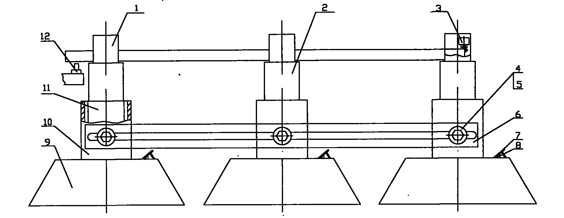
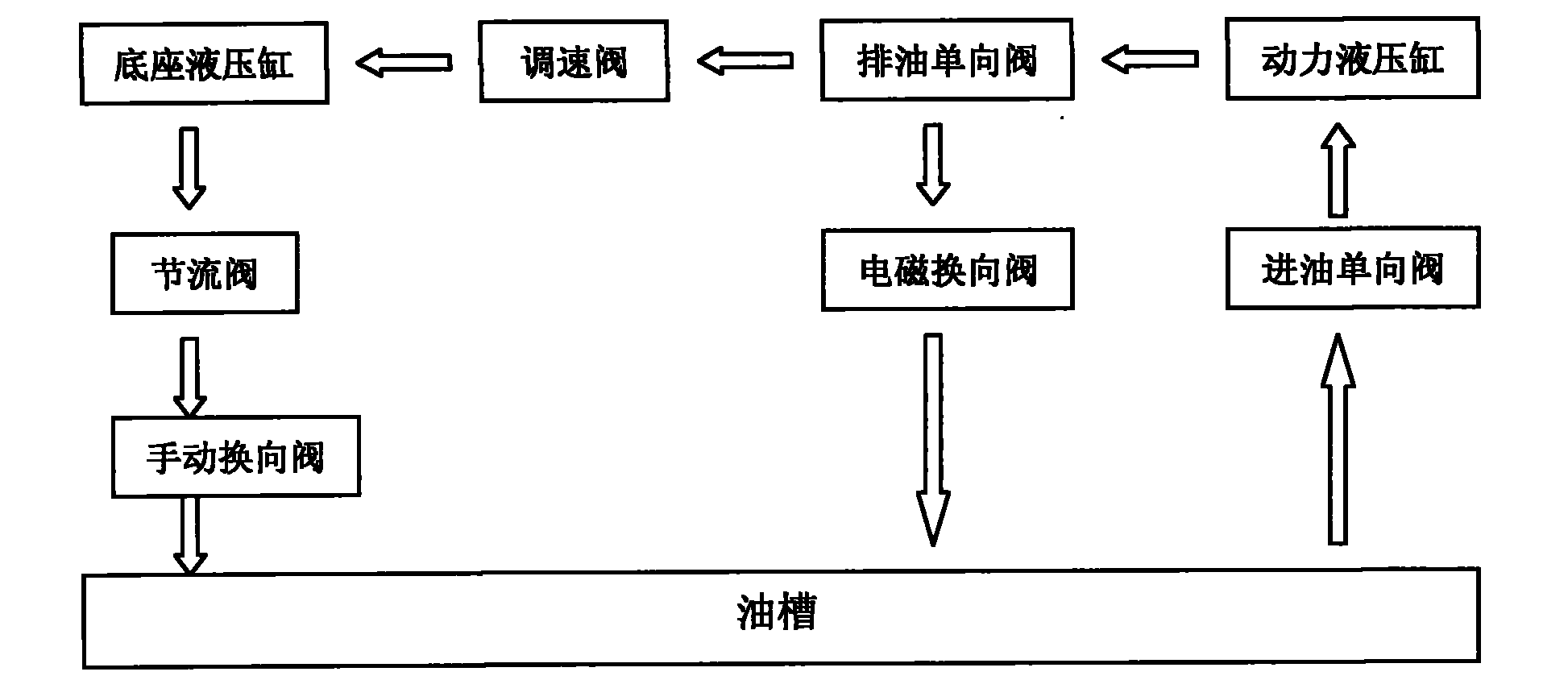
[0015] Attached below figure 1 , 2 And 3 and embodiment further illustrate the present invention.

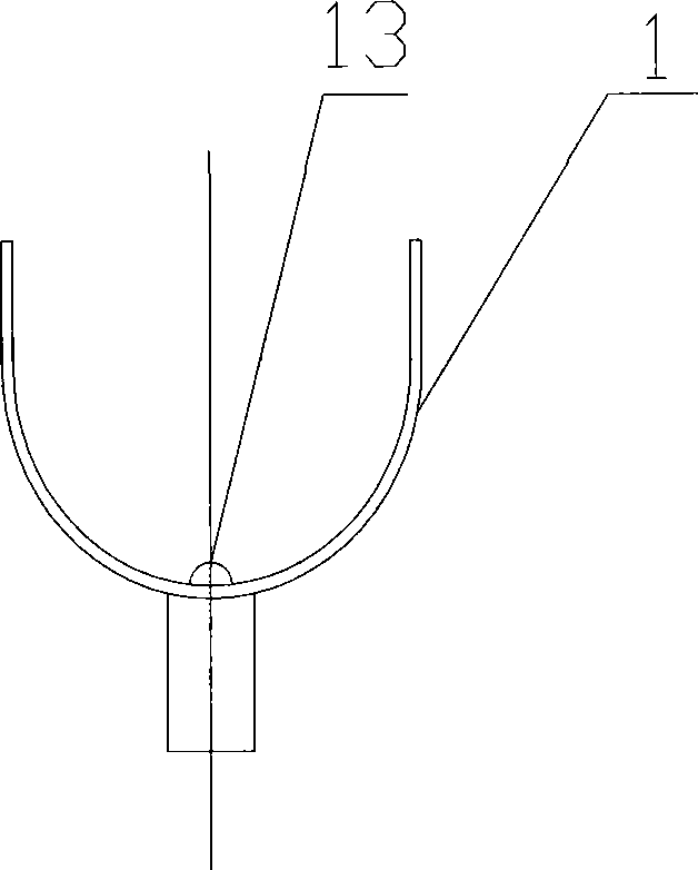
[0016] A support frame device for a spiral duct machine, which is mainly composed of a U-shaped frame 1, a lifting pipe 2, a base 9, a track steel 6, a pedal 7, a travel switch 3 and a cutting machine 12, and is characterized in that: the U-shaped frame 1 When rising, stepping on the pedal 7 on the upper surface edge of the base 9 drives the power part 8 of the hydraulic system in the base 9 to move up and down. At this time, the hydraulic oil enters the power hydraulic cylinder through the oil tank and the oil inlet check valve, and then passes through the oil discharge sheet The direction valve and speed regulating valve flow into the hydraulic cylinder of the base, and the hydraulic oil acts on the lower end of the lifting pipe 2. The lower end of the lifting pipe 2 and the sealing pipe 11 welded in the middle of the base 9 realize the piston movement, so that the lifting pi...


PUM


Abstract

The invention provides a spiral duct machine support frame, and aims to provide a device can adjust the longitudinal and transverse movement of each support frame and can realize automatic spiral duct cutting. The support frame device is composed of U-shaped frames, lifting pipes, bases, rail steel, pedals, a travel switch and a cutting machine. The pedals drive the execution parts lifting pipes through hydraulic systems in the bases, and the lifting pipes drive the U-shaped frames to rise. When the U-shaped frames reach preset positions, contact switches on the U-shaped frames touch a spiral duct, the U-shaped frames stop rising, and an electromagnetic directional valve is opened. When the U-shaped frames descend, the electromagnetic directional valve is closed, a hand-directional valve is opened, and at the same time a throttle valve is adjusted so as to make the U-shaped frames descend to desired locations slowly. The number and interval of the support frame can be adjusted according to the length of the processed spiral duct pipe and the support frame strength requirement, and the support frame is fixed with screws and gaskets through the rail steel, the bases and threaded holes on positioning pipes. And when the front end of the spiral duct touches the travel switch, the cutting machine cuts off the spiral duct.

Description

technical field [0001] The invention relates to a support frame device, in particular to a support frame device used in the production of spiral air ducts, and belongs to the technical field of pipe making machines. Background technique [0002] The spiral air duct is a thin-walled tube made of a spiral bite with a metal tape. It is round, no welding, no air leakage, and no water leakage. It is mostly used for air supply and bulk material transportation, replacing the traditional white iron pipe (that is, manual bite iron pipe). The spiral air duct is a kind of air duct, and the whole machine straight pipe does not need to be knocked by hand. Its main purposes are: air supply includes ventilation, such as fresh air supply and exhaust, cold air supply, oil fume exhaust, dust removal, and bulk material transportation. [0003] When the spiral duct is produced, the strip-shaped sheet is output through the host machine and the uncoiler. The output pipe body generally has a lon...

Claims


Application Information

Patent Timeline
Patent Type & Authority Applications(China)
IPC IPC(8): B21C37/12
Inventor 王匀朱旻吴俊峰李季许桢英陈万荣朱启星郭云霞
Owner 江苏启星新型材料科技有限公司
Learn More