An Electromagnetic Relay with Contact Bias Placement

A technology of electromagnetic relays and contacts, applied in the direction of electromagnetic relays, electromagnetic relay details, relays, etc., can solve the problems of shortening the operating life of the motion mechanism, affecting the electrical performance of the relay, and affecting the stability of the motion, so as to improve the electrical performance index , to ensure stability, to avoid the effect of movement

Active Publication Date: 2015-10-28
XIAMEN HONGFA ELECTROACOUSTIC CO LTD
View PDF5 Cites 0 Cited by
  • Summary
  • Abstract
  • Description
  • Claims
  • Application Information

AI Technical Summary

Problems solved by technology

Since F1 and F2 are not completely parallel to the movement direction (horizontal direction) of the push card, the push card cannot move smoothly horizontally during the process of setting and releasing the push card driven by the armature part, and it must move in the vertical direction. There is movement on the surface, which affects the movement stability of the entire mechanism, shortens the operating life of the movement mechanism, and causes the moving contact driven by the push card to move in the vertical direction, thereby affecting the electrical performance of the relay

Method used


Image

  • An Electromagnetic Relay with Contact Bias Placement
  • An Electromagnetic Relay with Contact Bias Placement
  • An Electromagnetic Relay with Contact Bias Placement

Examples


Embodiment Construction

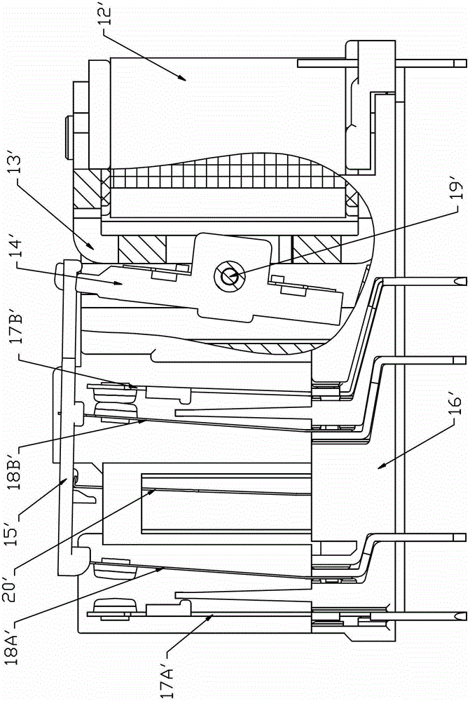
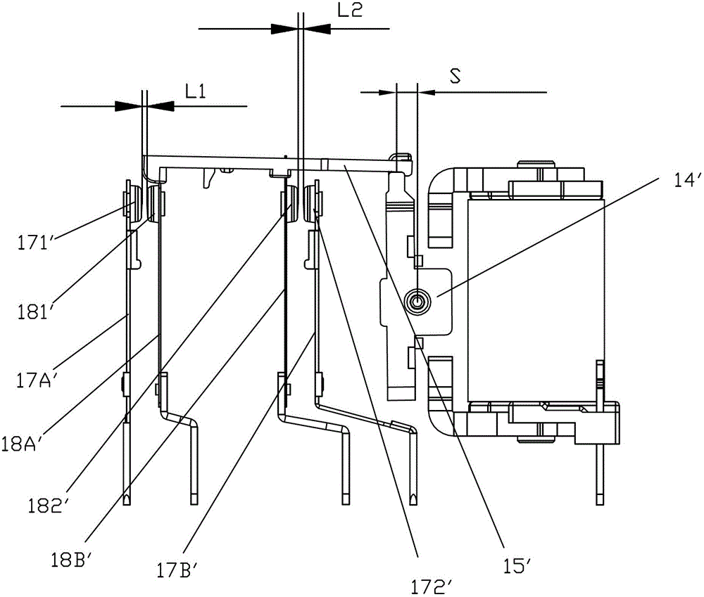
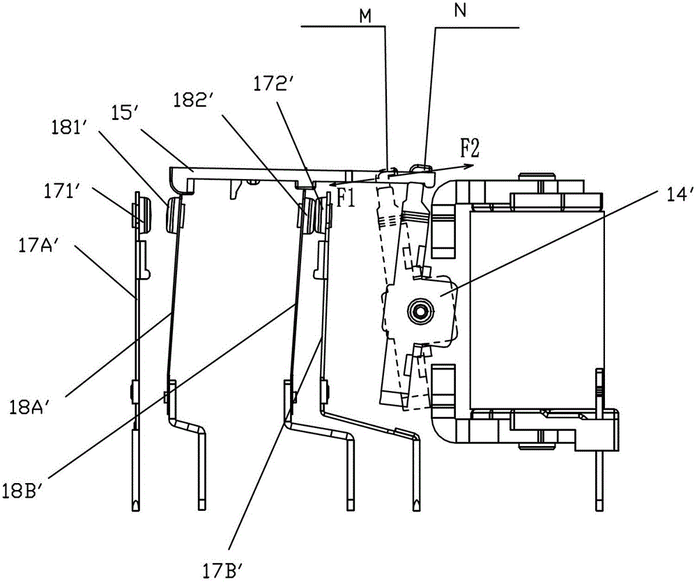
[0054] Examples, see Figure 3 to Figure 15 As shown, an electromagnetic relay with biased contacts of the present invention includes a magnetic circuit part 1, a base 21, a static spring assembly and a push card part 3; the magnetic circuit part 1 includes a coil 11, a yoke 12 and an armature part 13 , wherein the armature part is provided with a central rotating shaft 131 that can make it rotate, and the armature part 13 is rotatably positioned on the base 21 through the central rotating shaft 131 provided on the armature part, and of course it can also be positioned on other supportable bodies The static spring combination includes a normally open static spring combination 22 and a normally closed static spring combination 23, and the normally open static spring combination 22 is composed of a normally open static spring sheet 221 and a normally open static contact 222 fixed on the normally open static spring sheet The normally closed static spring combination 23 is compose...


PUM


Abstract

The invention discloses an electromagnetic relay with contacts bias placed. The electromagnetic relay comprises a magnetic circuit part, a base, a pushing clamping part and a stationary spring assembly. The stationary spring assembly comprises a normally open stationary spring assembly and a normally closed stationary spring assembly. The magnetic circuit part comprises a coil, a yoke iron and an armature part. In the process of excitation, the armature part rotates forward or backward and drives the pushing clamping part to move forward or backward. The pushing clamping part comprises a pushing clamp, a normally open contact chip part, a normally closed contact chip part and a spring. A normally open movable contact and a normally closed movable contact respectively correspond to a normally open stationary contact and a normally closed stationary contact. When the armature part is neutral, the pushing clamp is installed on the base, and a contact gap L1 between the normally open movable contact and the normally open stationary contact is not equal to a contact gap L2 between the normally closed movable contact and the normally closed stationary contact. By means of such a structure, normally open contact ends and normally closed contact ends can acquire the same indexes such as contact over-travel, contact pressure and the like in the process of setting and release (resetting) while the relay does not need to be especially adjusted after being assembled, and therefore the normally open contact ends and the normally closed contact ends can be consistent in electrical property.

Description

technical field [0001] The invention relates to an electromagnetic relay, in particular to an electromagnetic relay with contact bias placement. Background technique [0002] Existing electromagnetic relays such as figure 1 as shown, figure 1 It is a structural schematic diagram of a typical electromagnetic relay at present, which is composed of a magnetic circuit part, a base part and a push card part; wherein, the base part includes a base 16', a normally open static spring combination 17A', and a normally closed static spring combination 17B' , normally open moving spring combination 18A', normally closed moving spring combination 18B' and return reed 20'; the magnetic circuit part is composed of a coil 12', a yoke 13' and an armature part 14'; the armature part 14' can be inserted along its center The installed metal rotating shaft 19' rotates; the push card part is played by a push card 15' with a card slot. When the coil 12' is energized and the armature is driven t...

Claims


Application Information

Patent Timeline
Patent Type & Authority Patents(China)
IPC IPC(8): H01H50/64
Inventor 蔡文智谭忠华刘金枪
Owner XIAMEN HONGFA ELECTROACOUSTIC CO LTD
Why Eureka
Try Eureka