
Device and method for reducing small casting blank molten steel impact depth

A technology for molten steel and casting billets, which is applied in the field of devices for slowing the impact depth of molten steel in small billets, can solve the problems of reduced service life, increased costs, and reduced flow rate of molten steel, and achieves the effects of uniform temperature, slowing impact depth, and reducing internal stress.

Inactive Publication Date: 2014-04-09
ANGANG STEEL CO LTD
View PDF7 Cites 2 Cited by
  • Summary
  • Abstract
  • Description
  • Claims
  • Application Information

AI Technical Summary

Problems solved by technology

However, when adding a spiral diversion structure in the nozzle, its impact on various aspects must be fully considered: 1. The existence of the diversion structure will reduce the flow rate of molten steel; 2. Due to working in high-temperature and high-speed molten steel, the material of the diversion structure The requirements are also quite high, otherwise the service life will be reduced, which will increase the cost; 3. The broken diversion structure may also become a source of new inclusions in the slab

Method used


Image

  • Device and method for reducing small casting blank molten steel impact depth
  • Device and method for reducing small casting blank molten steel impact depth
  • Device and method for reducing small casting blank molten steel impact depth

Examples


Embodiment 1

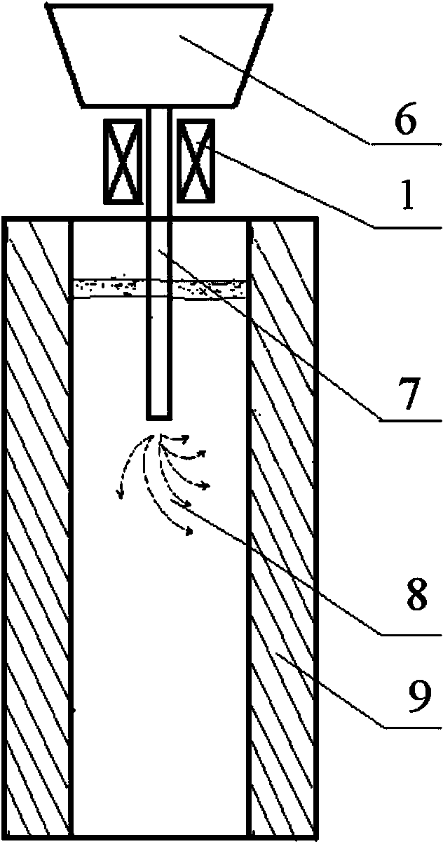
[0026] The specific parameters of the outlet electromagnetic stirrer 1 designed for 120×120mm billet are shown in Table 1.

[0027] Table 1. Parameters of 120×120mm Billet Nozzle Electromagnetic Stirrer

[0028] name parameter Stirrer box inner diameter mm Ф150 Stirrer box outer diameter mm Ф400 Stirrer box height mm 150 power supply Two-phase power Frequency Hz 50 Coil current A 40

[0029] The installation position of the electromagnetic stirrer 1 is as follows: image 3 shown. Because the electromagnetic stirrer 1 needs to be cooled by water, in order to prevent the temperature from dropping too fast near the nozzle, the electromagnetic stirrer 1 can be wrapped with refractory felt or other heat-insulating and high-temperature-resistant materials. Set the current size and frequency of the electromagnetic stirrer 1 before starting casting. Turn on the power supply of the electromagnetic stirrer 1 during ca...

Embodiment 2

[0031] The specific parameters of the outlet electromagnetic stirrer 1 designed for 160×160mm billet are shown in Table 2.

[0032] Table 2. Parameters of 160×160mm Billet Nozzle Electromagnetic Stirrer

[0033] name parameter Stirrer box inner diameter mm Ф180 Stirrer box outer diameter mm Ф450 Stirrer box height mm 160 power supply Three-phase 380V industrial electricity Frequency Hz 30 Coil current A 50

Embodiment 3

[0035] The specific parameters of the nozzle electromagnetic stirrer 1 designed on the Ф150mm round billet are shown in Table 3.

[0036] Table 3. Parameters of Electromagnetic Stirrer at Ф150mm Round Billet Nozzle

[0037] name parameter Stirrer box inner diameter mm Ф160 Stirrer box outer diameter mm Ф420 Stirrer box height mm 150 power supply Three-phase 380V industrial electricity Frequency Hz 100 Coil current A 30


PUM


Abstract

The invention provides a device and method for reducing the casting blank molten steel impact depth. The device is composed of electromagnetic stirrers, a pincerlike handle, a pin shaft and a support. The front portion of a straight rod and the front portion of a bent rod of the pincerlike handle are hinged together through the pin shaft, and the front end of the straight rod and the front end of the bent rod are respectively and fixedly provided with one semicircular electromagnetic stirrer. Before casting, the two semicircular electromagnetic stirrers are installed outside a water gap between a tundish and a crystallizer in an opposite buckling mode. During casting, the electromagnetic stirring current is controlled to be 20-400A, the stirring frequency is controlled to be 1-100 Hz, and the stirring power is determined according to the horizontal-direction speed V1 and the vertical-direction speed V2 of molten steel, and V1 / V2 ranges from 0.5 to 2. The device and method for reducing the casting blank molten steel impact depth are easy to implement, have no pollution, and can effectively reduce the impact depth of small square billet water gap molten steel, facilitate upward floating of gas and impurities in the molten steel, reduce the content of gas and impurities in solidified casting blanks, reduce casting blank defects and internal stress, and improve casting blank quality.

Description

technical field [0001] The invention belongs to the technical field of continuous casting technology, and in particular relates to a device and method for slowing down the impact depth of billet molten steel. Background technique [0002] The role of the mold is to undertake the injection of molten steel flowing out of the tundish. The flow field of the molten steel in the mold not only has an important impact on the behavior of the steel-slag interface in the mold, but also has a great influence on the solidification heat transfer in it, so The flow state of molten steel in the mold directly affects the surface quality and internal quality of the slab. [0003] Billet and round billet continuous casting molds are small in size, so straight nozzles are generally used. During the casting process, the molten steel flows out from the tundish, and is directly poured into the mold through the nozzle. Under the action of inertial force, the molten steel stream will rush into a re...

Claims


Application Information

Patent Timeline
IPC IPC(8): B22D11/115
Inventor 郭庆涛廖相巍王琼贾吉祥黄玉平唐雪峰张宇
Owner ANGANG STEEL CO LTD
Learn More