Combined screw

A technology of screws and non-threaded parts is applied in the field of connectors, which can solve problems such as complex structures, achieve high creepage distance, realize automatic production and easy operation.

Inactive Publication Date: 2014-04-02
SHENZHEN SINE ELECTRIC
View PDF8 Cites 3 Cited by
  • Summary
  • Abstract
  • Description
  • Claims
  • Application Information

AI Technical Summary

Problems solved by technology

[0004] The technical problem to be solved by the present invention is to provide a combination screw with simple structure and convenient processing and assembly in view of the defect that the structure of the above-mentioned connector in the prior art is relatively complicated to realize the electrical isolation between it and the heat sink.

Method used


Image

  • Combined screw
  • Combined screw
  • Combined screw

Examples


Embodiment Construction

[0024] In order to have a clearer understanding of the technical features, purposes and effects of the present invention, the specific implementation manners of the present invention will now be described in detail with reference to the accompanying drawings.

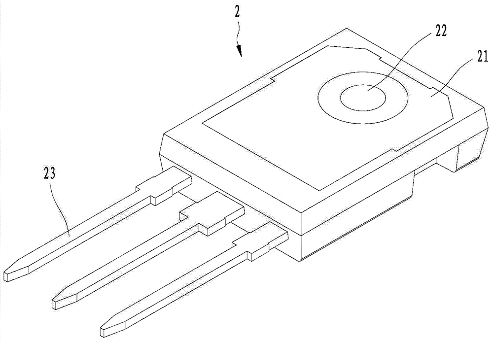
[0025] Such as image 3 , Figure 4 , Figure 5 as well as Figure 6 As shown, the preferred embodiment of the present invention provides a combination screw 1 for fixing the chip 2 on the heat dissipation base 3 . The combination screw 1 includes a head 11 and a shank 12 . One side of the chip 2 is provided with a heat sink 21, and the chip 2 also includes a fixing hole 22 set through the heat sink 21, and the fixing hole 22 extends from the side of the chip 2 provided with the heat sink 21 to the other opposite side. . When the combination screw 1 passes through the fixing hole 22 to fix the chip 2 on the heat dissipation base 3, the heat sink 21 and the heat dissipation base 3 are attached to each other to reali...


PUM


Abstract

The invention discloses a combined screw. The combined screw is used for fixing a chip on a heat radiating base; one side surface of the chip is provided with a heat radiating sheet which is attached with the heat radiating base, and the chip is provided with a fixing hole penetrating through the heat radiating sheet. The combined screw comprises a head part, a rod part and an insulation layer, wherein the insulation layer is arranged on the outer wall of one end, near the head part, of the rod part in a coating manner. When the combined screw penetrates through the fixing hole to fix the chip on the heat radiating base, the insulation layer is positioned between the heat radiating sheet and the rod part. The combined screw has the beneficial effects that by adopting the structure of the insulation layer arranged on the outer wall of one end, near the head part, of the rod part in a coating manner, the electric insulation between the combined screw and the heat radiating sheet is realized, and a longer creepage distance is realized; the structure is simple; when the chip is assembled with a thread connection method, the operation is easy and convenient, and the automatic production is favorably realized.

Description

technical field [0001] The invention relates to the technical field of connectors, in particular to a combination screw for fixing a chip on a heat dissipation base. Background technique [0002] Low-power inverter circuits usually use IGBT (insulated gate bipolar transistor) chips 2 , and chips 2 packaged in TO series are mainstream products in the industry. Such as figure 2 As shown, a heat sink 21 is provided on one side of the chip 2, and the heat sink 21 usually adopts a heat dissipation copper substrate. In a common chip 2 , the heat sink 21 is connected to the pin 23 . Therefore, when the chip 2 is in a working state, the charged voltage on the heat sink 21 is the same as the charged voltage on the pin 23 . In the prior art, connectors are usually used to fix the chip 2 on the heat dissipation base 3. At this time, it is necessary to effectively electrically isolate the heat sink 2 from the connectors to avoid short circuits caused by the connectors contacting other...

Claims


Application Information

Patent Timeline
Patent Type & Authority Applications(China)
IPC IPC(8): F16B35/04F16B35/06H01L23/40
Inventor 陈飞
Owner SHENZHEN SINE ELECTRIC
Why Eureka
Try Eureka