Antifouling clamping block of continuous tube injection head and manufacturing method thereof

A clamping block and injection head technology, which is applied in the direction of drill pipe, casing, earthwork drilling and mining, etc., can solve the problems of clamping block clamping performance degradation, etc., to reduce the loss of clamping performance and reduce the clamping contact area , Guarantee the effect of clamping performance stability

Inactive Publication Date: 2014-03-26
BC P INC CHINA NAT PETROLEUM CORP +2
View PDF4 Cites 7 Cited by
  • Summary
  • Abstract
  • Description
  • Claims
  • Application Information

AI Technical Summary

Problems solved by technology

[0004] In order to solve the problems of the prior art, the embodiment of the present invention provides an anti-pollution clamping block of the coiled tubing injection head, which can overcome the problem of the clamping performance reduction of the clamping block caused by downhole medium contamination

Method used


Image

  • Antifouling clamping block of continuous tube injection head and manufacturing method thereof
  • Antifouling clamping block of continuous tube injection head and manufacturing method thereof
  • Antifouling clamping block of continuous tube injection head and manufacturing method thereof

Examples


Embodiment 1

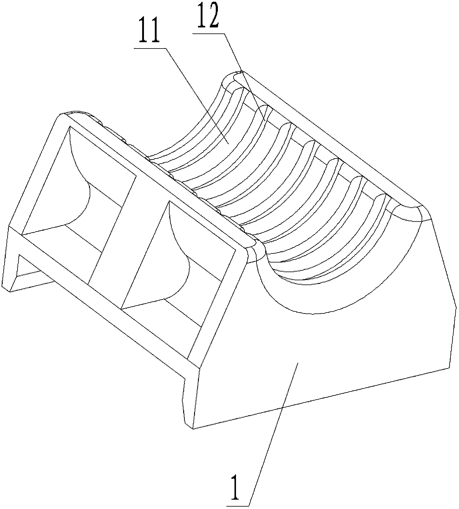
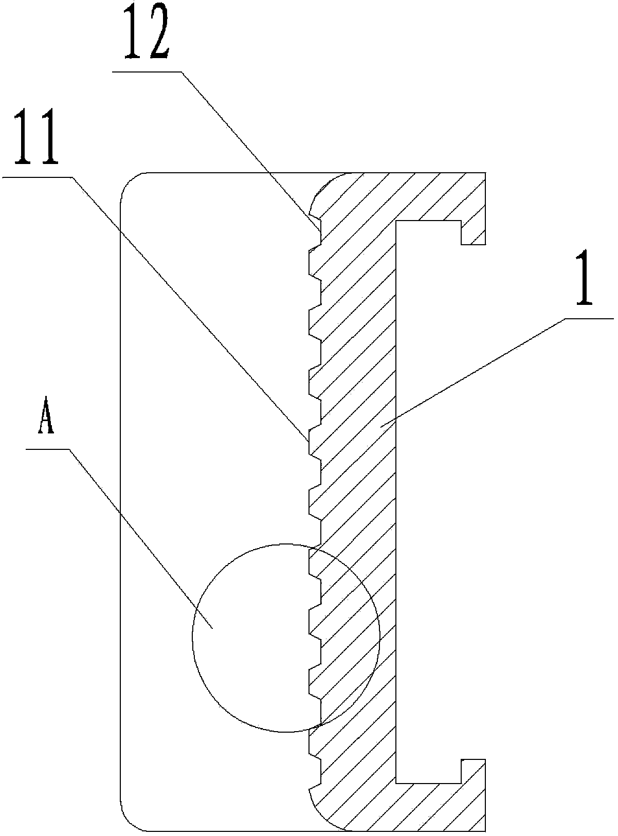
[0024] This embodiment provides a kind of anti-fouling clamping block of coiled tubing injection head, see figure 1 , figure 2 and image 3 , the anti-pollution clamping block includes: a clamping block body 1, the clamping block body 1 has a concave arc clamping surface 11, the concave arc clamping surface 11 and another concave arc clamping surface 11 or anti-pollution Other parts of the clamping block cooperate to clamp the injection head of the coiled tubing.

[0025] A transverse groove 12 is processed on the concave arc clamping surface 11, that is, the transverse groove 12 is arranged radially along the concave arc clamping surface 11, and multiple transverse grooves 12 are spaced apart on the concave arc clamping surface 11 It is set that the distance between every two transverse grooves 12 is 5mm-10mm. Preferably, the depth of the transverse groove 12 is 1.5 mm to 2.5 mm, and the width is 3.0 mm to 8.0 mm, and the bottom surface from the concave circular arc clamp...

Embodiment 2

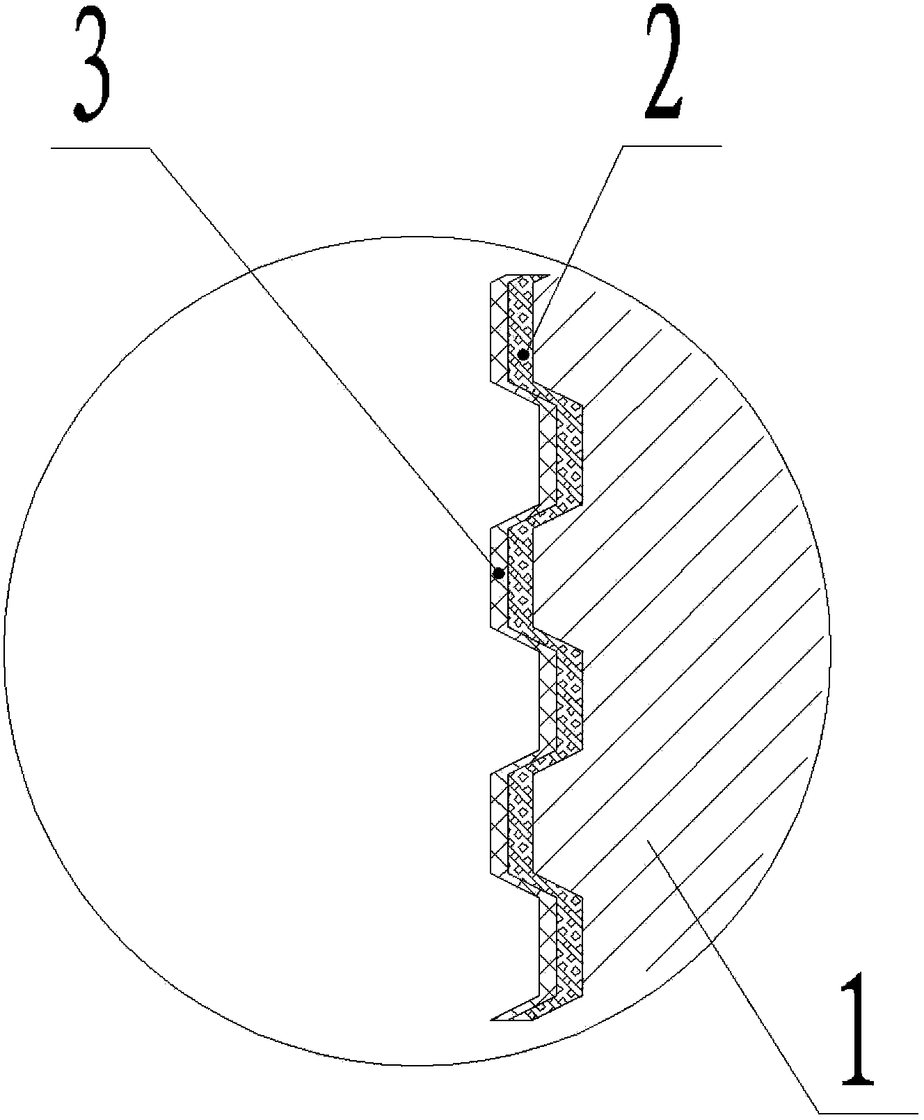
[0028] The embodiment of the present invention provides a method for manufacturing an anti-fouling clamping block of a coiled tubing injection head, the method mainly includes a method of arranging a frictional coating 2 and a corrosion-resistant and anti-fouling coating 3 on the anti-fouling clamping block. see figure 1 , figure 2 and image 3 , the friction coating 2 is set on the concave arc clamping surface 11 and the bottom surface and side wall of the transverse groove 12 by spraying, including:

[0029] S701, cleaning, degreasing and sandblasting roughening of the concave arc clamping surface 11 first, the roughening degree is Ral2.5. In this way, oil stains and scales on the surface of the concave arc clamping surface can be effectively removed, so that the adhesion of the friction coating on the concave arc clamping surface is better.

[0030] S702, using 325 mesh to 500 mesh WC-Co alloy powder for supersonic spraying, the process parameters during spraying are: O...


PUM

PropertyMeasurementUnit
Thicknessaaaaaaaaaa
Granularityaaaaaaaaaa

Abstract

The invention discloses an antifouling clamping block of a continuous tube injection head. The antifouling clamping block comprises a clamping block body (1) which is provided with a concave arc clamping face (11), a transverse groove (12) is formed in the concave arc clamping face (11), and a friction coating layer (2) and an anticorrosion and antifouling coating layer (3) are arranged on the concave arc clamping face (11) in sequence. The invention further discloses a manufacturing method of the antifouling clamping block of the continuous tube injection head, and belongs to the field of well drilling device corollary equipment. Due to the fact that the transverse groove is formed in the concave arc clamping face, the clamping contact area is reduced, unit pressure on the contact face is increased, the continuous lubrication film layer formed by underground media on the clamping surface can be effectively blocked and damaged, and stability of clamping performance is improved.

Description

technical field [0001] The invention relates to the field of supporting equipment for drilling equipment, in particular to an anti-pollution clamping block of a coiled tubing injection head, which is especially suitable for a chain clamping system of a winding connecting pipe. The invention also relates to a method for manufacturing the anti-fouling clamping block of the injection head of the coiled tubing. Background technique [0002] The coiled tubing injection head system is an important basic component for leading the drum-wound coiled tubing into the operation well or exporting it from the operation well to the drum for winding. The injection head clamping block mainly plays the role of clamping and leading in and out of the coiled tubing, preventing relative sliding between the coiled tube and the clamping block. With the popularization and application of coiled tubing technology in oil and gas fields, the wall of downhole coiled tubing is relatively clean in natural...

Claims


Application Information

Patent Timeline
IPC IPC(8): E21B19/22C23C4/12C23C4/06B05D7/24B05D5/00
Inventor 袁文才贺会群石成刚熊革谭文锋罗刚任武
Owner BC P INC CHINA NAT PETROLEUM CORP
Why Eureka
Try Eureka