
Controllable sand flow infinitely variable speed fan blade abrasion testing device

A technology of infinitely variable speed and fan blades, which is applied in the direction of testing wear resistance, etc., to achieve the effects of reducing air pollution, stabilizing the flow field, and reducing the amount of dust

Inactive Publication Date: 2014-03-19
JILIN UNIV
View PDF3 Cites 10 Cited by
  • Summary
  • Abstract
  • Description
  • Claims
  • Application Information

AI Technical Summary

Problems solved by technology

[0009] The purpose of the present invention is to provide a controllable sand flow continuously variable speed fan blade erosion test device in order to overcome a series of technical problems that the existing erosion wear test device cannot truly simulate the erosion and wear condition of the fan rotating blade

Method used


Image

  • Controllable sand flow infinitely variable speed fan blade abrasion testing device
  • Controllable sand flow infinitely variable speed fan blade abrasion testing device
  • Controllable sand flow infinitely variable speed fan blade abrasion testing device

Examples


Embodiment 1

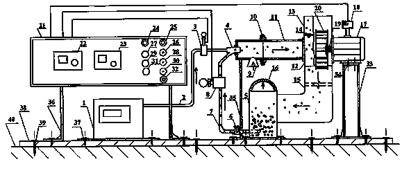
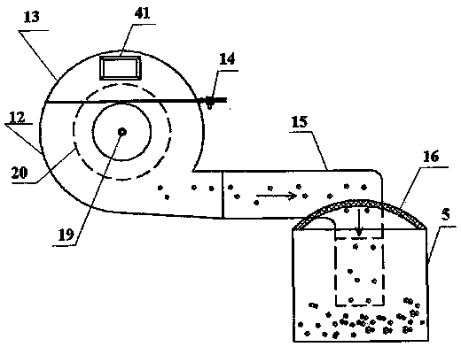
[0040] see figure 1 , figure 2 and image 3 As shown, this embodiment is a test of the erosion performance of centrifugal fan blades.

[0041] This embodiment is composed of air compressor 1, gas delivery pipe 2, pressure sensor 3, spray gun 4, sand storage chamber 5, sand flow control valve 6, sand pipe 7, particle flow sensor 8, air intake pipe 11, erosion and wear Test room 12, erosion wear test room upper cover 13, air outlet pipe 15, dust collector 16, motor 17, frequency converter 18, fan impeller 20, control cabinet 21, motor support 33, intake pipe support 35, control cabinet support 36 , angle iron frame 38 components;

[0042] Among them, the air compressor 1, the gas delivery pipe 2, the air pressure sensor 3, the spray gun 4, the air intake pipe 11, and the erosion wear test chamber 12 are connected in sequence, and the air inlet 9 is arranged under the air intake pipe 11, and the erosion wear test chamber The cover 13 is movably installed on the upper part of...

Embodiment 2

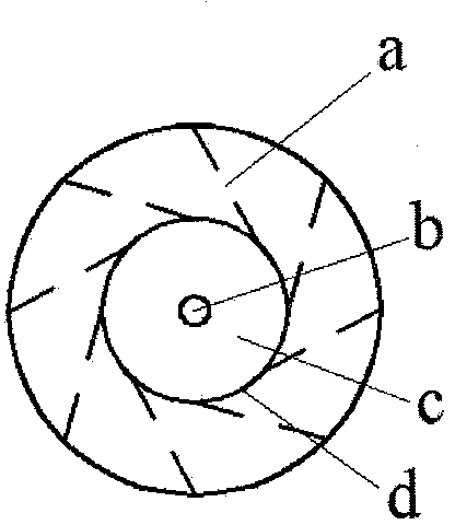
[0050] see figure 1 , figure 2 and Figure 4 As shown, this embodiment is an erosion performance test of an axial flow fan blade.

[0051] This embodiment is composed of air compressor 1, gas delivery pipe 2, pressure sensor 3, spray gun 4, sand storage chamber 5, sand flow control valve 6, sand pipe 7, particle flow sensor 8, air intake pipe 11, erosion and wear Test room 12, erosion wear test room upper cover 13, air outlet pipe 15, dust collector 16, motor 17, frequency converter 18, fan impeller 20, control cabinet 21, motor support 33, intake pipe support 35, control cabinet support 36 , angle iron frame 38 components;

[0052] Among them, the air compressor 1, the gas delivery pipe 2, the air pressure sensor 3, the spray gun 4, the air intake pipe 11, and the erosion wear test chamber 12 are connected in sequence, and the air inlet 9 is arranged under the air intake pipe 11, and the erosion wear test chamber The cover 13 is movably installed on the upper part of the...


PUM


Abstract

The invention discloses a controllable sand flow infinitely variable speed fan blade abrasion testing device which consists of an air compressor, a gas delivery pipe, a pressure sensor, a spray gun, a sand storage chamber, a sand flow control valve, a sand pipe, a particle flow sensor, an air inlet pipeline, an erosive wear test chamber, an erosive wear test chamber upper cover, an air outlet pipeline, a deduster, a motor, a frequency converter, a fan propeller, a control cabinet, a motor bracket, an air inlet pipeline bracket, a control cabinet bracket and an angle iron bracket. A series of technical problems that the erosive wear working conditions of a rotary fan blade cannot be really simulated by a conventional erosive wear testing device are overcome.

Description

technical field [0001] The invention relates to a testing technology for the erosion and wear performance of materials, in particular to a test device for erosion of blades of a continuously variable speed fan with controllable sand flow. Background technique [0002] The starting point of the research on the erosion test device of fan blades is to analyze the gas / solid erosion wear performance and erosion wear mechanism of fan blades with different materials, configurations and shapes, and to research and develop new erosion-resistant materials and new anti-erosion wear materials. method. [0003] The erosion wear and protection of materials has always been the focus of research. In the fields of machinery, metallurgy, energy, building materials, etc., due to the erosion wear of materials, especially the erosion wear damage of fan blades, it will cause huge waste and waste every year. loss. Therefore, to study the erosion wear characteristics and mechanism of fan blades, ...

Claims


Application Information

Patent Timeline
Patent Type & Authority Applications(China)
IPC IPC(8): G01N3/56
Inventor 韩志武张俊秋尹维刘庆萍江佳廉付君任露泉
Owner JILIN UNIV
Learn More