
Positioning Water Spray Device of Reciprocating Wire EDM Machine Tool

A technology for wire EDM and cutting machine tools, used in attachments, electric processing equipment, metal processing equipment, etc., can solve problems such as product quality impact, jitter, wire breakage, etc., to improve surface accuracy and product quality, reduce chattering The effect of small amplitude and jitter amplitude

Active Publication Date: 2016-10-05
自贡市嘉特数控机械制造有限公司
View PDF10 Cites 0 Cited by
  • Summary
  • Abstract
  • Description
  • Claims
  • Application Information

AI Technical Summary

Problems solved by technology

Therefore, all reciprocating wire EDM machine tools are equipped with water spray devices. With the development of "medium wire cutting" technology, the traditional water spray devices that can only meet the cooling effect of water spray can no longer fully meet the requirements of "multiple cutting". The requirements of the process, the disadvantages are: 1. There are many debris, which are easy to accumulate and block the water spray hole; the inner surface of the nozzle of the traditional water spray plate is a concave spherical surface, and the water spray hole is on the concave spherical surface. There is a lot of debris, if the cleaning is not enough, it will easily accumulate and block the water spray hole, resulting in poor water spray, unstable processing, and even broken wires; 2. The traditional water spray device has no electrode wire positioning function, because the electrode wire runs faster , there must be jitter, resulting in poor machining surface accuracy and affected product quality

Method used


Image

  • Positioning Water Spray Device of Reciprocating Wire EDM Machine Tool
  • Positioning Water Spray Device of Reciprocating Wire EDM Machine Tool
  • Positioning Water Spray Device of Reciprocating Wire EDM Machine Tool

Examples


Embodiment Construction

[0012] The present invention will be described in further detail below in conjunction with the accompanying drawings.

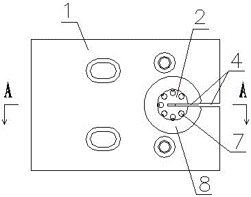
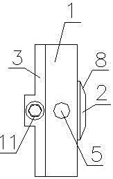
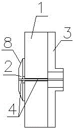
[0013] Such as Figure 1 to Figure 5 As shown, the positioning water spray device of the reciprocating wire electric discharge machine tool includes a water spray plate 1, a nozzle 2 installed in the water spray plate 1, a mounting plate 3 fixed on the water spray plate 1, and a water spray plate 1 and one side of the nozzle 2 are provided with a connected thread groove 4, the water spray plate 1 is provided with a liquid inlet channel 5, and the nozzle 2 is provided with a liquid guide groove 6 connected with the liquid inlet channel 5 and connected with the liquid guide groove 6 There are several spray holes 7, the spray end of nozzle 2 is located outside the end face of water spray plate 1, and chamfers 8 are provided on the nozzle end faces outside all spray holes 7; the water spray end of mounting plate 3 and nozzle 2 is located On the opposite sides of...


PUM


Abstract

The invention discloses a positioning water spray device for a reciprocating wire electric discharge wire cutting machine tool, which includes a water spray plate and a nozzle installed in the water spray plate, and one side of the water spray plate and the nozzle is provided with a connected wire groove. There is a liquid inlet channel in the water spray plate, and the nozzle is provided with a liquid guide groove connected with the liquid inlet channel and several spray holes connected with the liquid guide groove. It is characterized in that the water spray end of the nozzle is located outside the end surface of the water spray plate. There are chamfers on the end faces of the nozzles outside all the spray holes, and a mounting plate is fixed on the water spraying plate on the opposite side of the spraying end of the nozzle. There is a dovetail groove in the mounting plate, and the opening of the dovetail groove and the wire groove Consistent, the holding block is placed in the dovetail groove, and the set screw for fixing the holding block is arranged on the mounting plate, and the holding block is made of diamond material. The invention has the advantages of no chip accumulating in the nozzle, stable processing, and small buffeting amplitude of the electrode wire, and effectively improves the surface precision and product quality of the workpiece.

Description

technical field [0001] The invention relates to a water spray device for a reciprocating wire electric discharge wire cutting machine tool. Background technique [0002] The mechanism of WEDM is to use the principle of "discharge machining" to perform electric erosion (spark discharge) on conductive materials to achieve the purpose of processing. Wire EDM does not need to make forming electrodes. During processing, a metal wire (usually molybdenum wire) is used as a tool electrode to discharge sparks on the workpiece. The positive electrode of the pulse power supply is connected to the workpiece, and the negative electrode is connected to the electrode wire. It reciprocates at a certain speed, it continuously enters and leaves the discharge area, and at the same time sprays liquid medium between the electrode wire and the workpiece, the workpiece moves according to the trajectory determined by the program under the control of the computer, and finally obtains the desired sha...

Claims


Application Information

Patent Timeline
Patent Type & Authority Patents(China)
IPC IPC(8): B23H11/00B23H7/02
Inventor 李克君
Owner 自贡市嘉特数控机械制造有限公司
Learn More