
Die-cast product rigidity evaluation method and die-cast product

A strength evaluation and product technology, applied in the direction of strength characteristics, using stable torsion to test the strength of materials, casting molds, etc., can solve problems such as fracture and strength drop, achieve accurate evaluation, and shorten the operation time.

Inactive Publication Date: 2014-03-12
NSK LTD
View PDF8 Cites 8 Cited by
  • Summary
  • Abstract
  • Description
  • Claims
  • Application Information

AI Technical Summary

Problems solved by technology

[0004] Here, in order to reduce weight, steering columns are mostly made of die-casting parts of light metals such as aluminum or magnesium, and there are internal defects. Therefore, when excessive torque is applied, fractures may occur, and how to evaluate the strength becomes difficult. very important
[0005] In particular, as an internal defect of die castings, fractured chilled layers are known to cause a decrease in strength, and inspection of fractured chilled layers is required for strength evaluation.

Method used


Image

  • Die-cast product rigidity evaluation method and die-cast product
  • Die-cast product rigidity evaluation method and die-cast product
  • Die-cast product rigidity evaluation method and die-cast product

Examples


no. 1 Embodiment approach )

[0059] Hereinafter, a first embodiment of a method for evaluating the strength of a die cast product will be described with reference to the drawings.

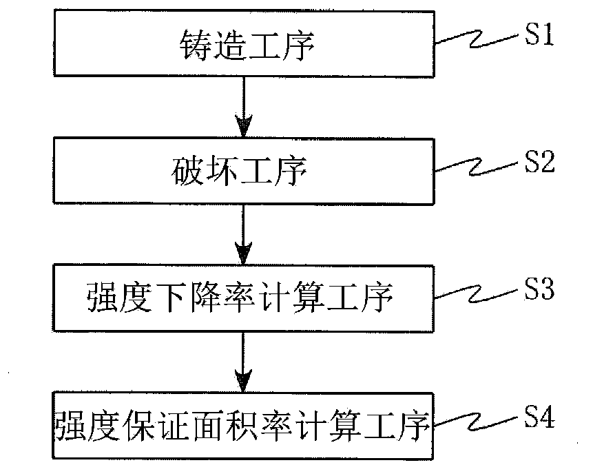
[0060] like figure 1 As shown, the present embodiment includes a casting step ( S1 ), a breaking step ( S2 ), a strength reduction rate calculation step ( S3 ), and a strength evaluation area ratio calculation step ( S4 ).

[0061]

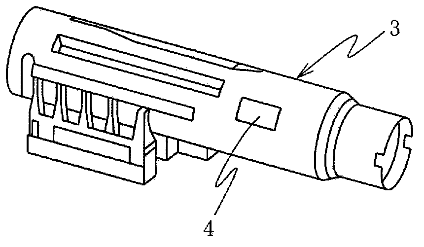
[0062] The casting process in this embodiment is a process of performing die casting using, for example, Al-Si-Cu-based aluminum alloy ADC12 of JIS H5302. The die-cast product obtained by this process is preferably figure 2 Steering column housing 3 of the shown vehicle handling device.

[0063]

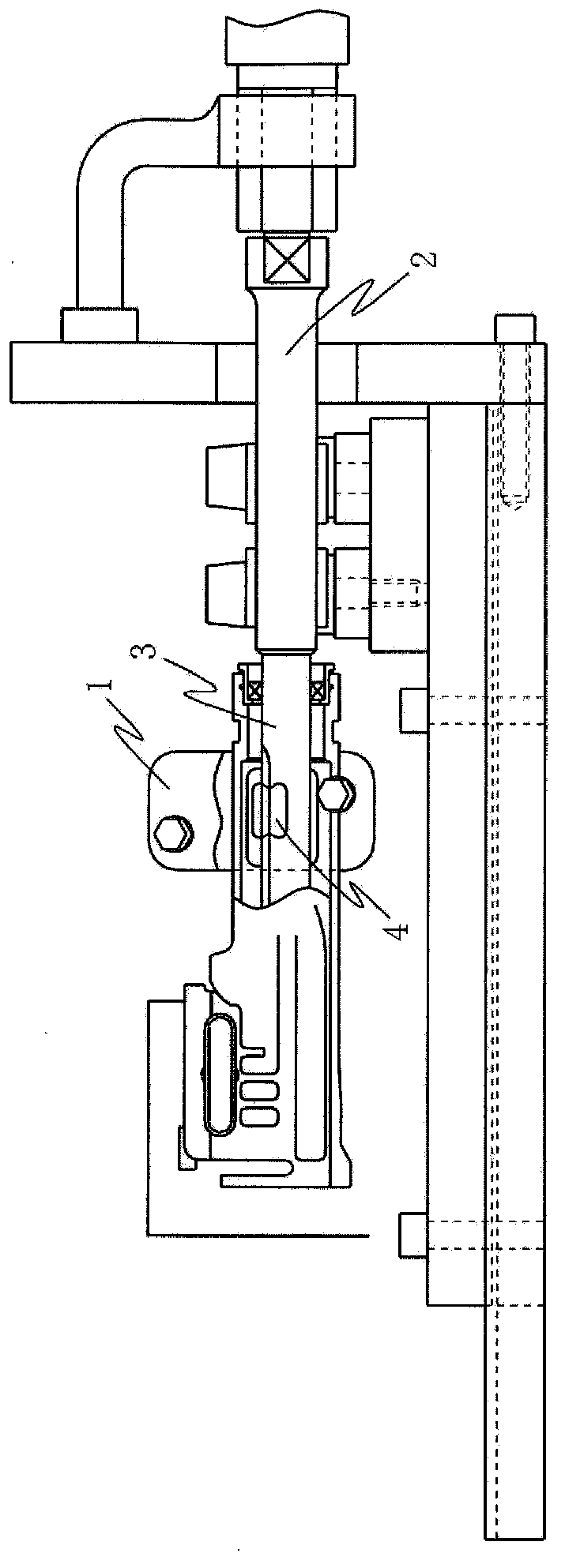
[0064] The breaking step in the present embodiment is a step of conducting a breaking test at the casting site of the die-cast product obtained by the casting step described above. The fracture test is preferably a torsion test.

[0065] The torsion test is specifically as image 3 As shown, th...

no. 2 Embodiment approach )

[0088] Next, a second embodiment of a method for evaluating the strength of a die cast product will be described with reference to the drawings.

[0089] Image 6 It is an explanatory diagram of the 6-axis movable ultrasonic flaw detector used in the strength evaluation method of the die-cast product of the present embodiment, Image 6 a is the overall diagram of the device, Image 6 b is a detailed diagram of the object to be tested and the rotary table, Image 6 c is an explanatory diagram of internal defect detection. Numeral 11 in the drawing is an aluminum die-cast product to be evaluated for strength in this embodiment, for example, a column housing of an electric power steering apparatus.

[0090]In the present embodiment, the aluminum die-cast product (column case) 11 is mounted above the turntable 12 , and the probe (probe) 13 is moved from above to below while the turntable 12 is rotated. The inner side of the casing) 11 is tested in a spiral shape. The die-cast...


PUM


Abstract

Provided are a die-cast product rigidity evaluation method and a die-cast product, the rigidity whereof is evaluated by the rigidity evaluation method, with which it is possible to appropriately evaluate the rigidity of a die-cast product. To this end, after carrying out a post-casting fracture test with a simple rigidity testing device, a rigidity deterioration rate is estimated on the basis of the proportion at which cold flakes are present on the fracture surface, which is obtained by observing a breakage surface. An internal defect of a prescribed range of a high-stress part of a die-cast product which is pre-derived with a stress analysis is detected with ultrasound, and when a defect rate which is the quotient of the total surface area of the internal defects of the prescribed range divided by the total defect detection surface area is less than or equal to a prescribed value, the die-cast product is evaluated as having a prescribed rigidity.

Description

technical field [0001] The present invention relates to a strength evaluation method of a die-cast product and a die-cast product (for example, a column housing made of aluminum die-cast) used in an electric power steering device of a vehicle. Background technique [0002] Conventionally, in order to prevent the theft of a car, a steering lock device is generally used, which not only stops the engine but also prevents the steering wheel from turning when the ignition key is pulled out. [0003] The main body of the steering lock device used in this way and the steering column as the attachment must be strong and not easily damaged. For example, it is stipulated in JIS D5812 or the like that the steering shaft is locked, and even if a torque of 200 Nm is applied to the steering shaft, the function cannot be abnormal. [0004] Here, in order to reduce weight, steering columns are mostly made of die-casting parts of light metals such as aluminum or magnesium, and there are int...

Claims


Application Information

Patent Timeline
Patent Type & Authority Applications(China)
IPC IPC(8): G01N3/22B22C9/24B22D17/00G01N29/04
CPCG01N29/07G01N3/22B22C19/04G01N2291/044B22C9/24G01N2291/0234B22D17/00G01N29/04G01N2291/02827G01N2203/0067G01N29/11B60R25/02115E05B15/1614
Inventor 三邑宗隆冲田滋内田启之
Owner NSK LTD
Learn More