
Active inductance type voltage-controlled oscillator

A voltage-controlled oscillator and active inductor technology, applied in power oscillators, electrical components, etc., can solve the problems of increasing the manufacturing cost of integrated circuits, difficult to achieve the performance indicators of communication systems, and large loss of coil metal.

Inactive Publication Date: 2014-03-12
HARBIN INST OF TECH
View PDF7 Cites 12 Cited by
  • Summary
  • Abstract
  • Description
  • Claims
  • Application Information

AI Technical Summary

Problems solved by technology

The on-chip passive inductor is made of metal wires wound on the Si substrate. Due to the limited thickness of the interconnection wire of the on-chip passive inductor, the metal loss of the coil is relatively large, and the skin effect is very significant. The coupling with the silicon substrate is very strong. Although the introduction of an external ground can shield the loss to a certain extent, the existence of these two loss mechanisms makes the inductance quality factor of the CMOS process low, generally only about a dozen, and passive It is difficult to adjust the inductance, and it occupies a large area of ​​the chip circuit, which increases the cost of integrated circuit manufacturing. At present, the passive LC structure on the chip is used, and it is still difficult to meet the performance indicators required by the communication system.

Method used


Image

  • Active inductance type voltage-controlled oscillator
  • Active inductance type voltage-controlled oscillator
  • Active inductance type voltage-controlled oscillator

Examples


Embodiment 1

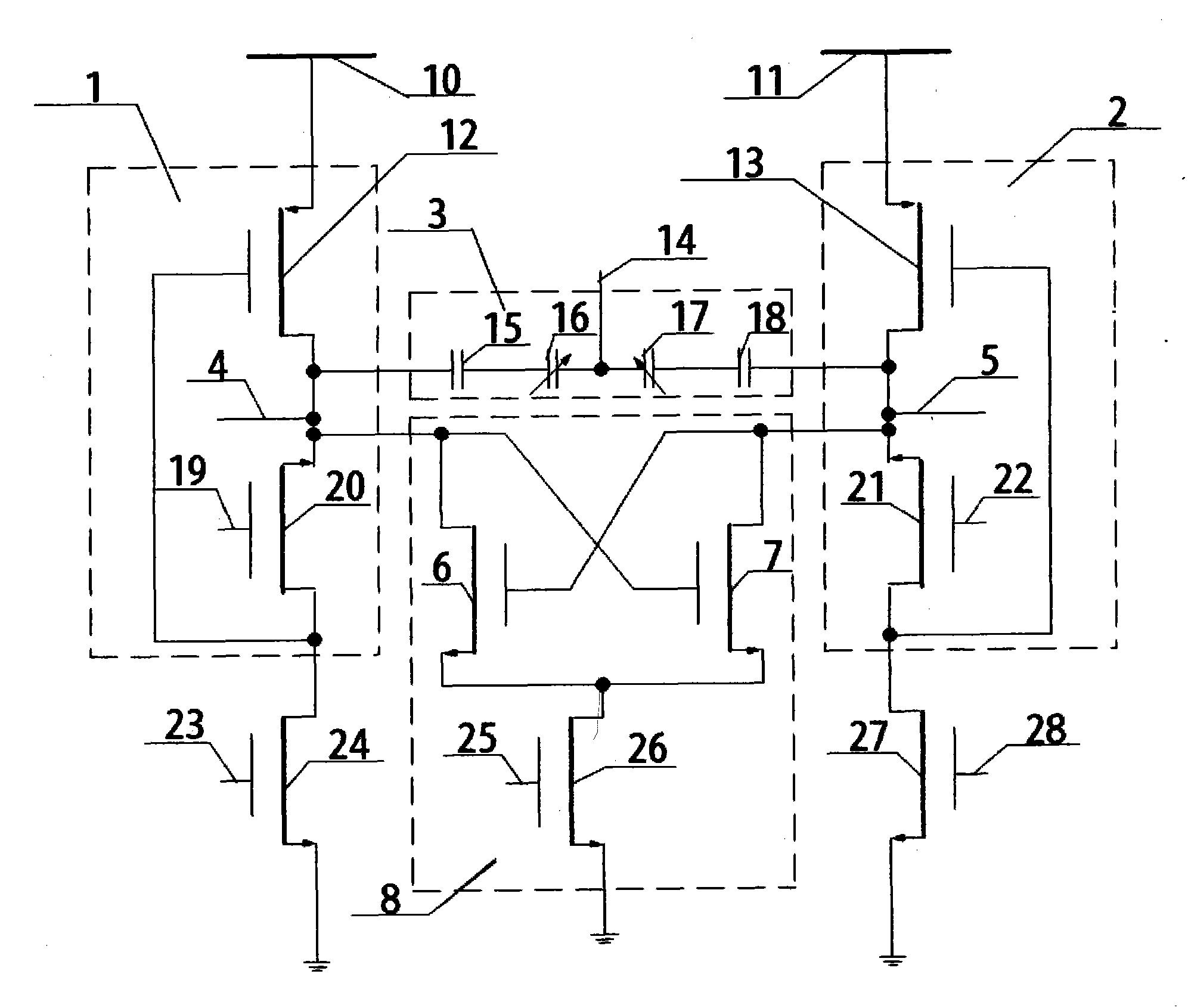
[0019] An active inductive voltage-controlled oscillator, comprising an LC resonant tank and a negative resistance circuit, the LC resonant tank comprising a first active inductance 1, a capacitor unit 3 and a second active inductance 2, the first active inductance One end of 1 is connected to the first high level 10, the other end of the first active inductance 1 is respectively connected to one end of the capacitor unit 3 and the first output end 4 of the voltage-controlled oscillator, and one end of the second active inductance 2 is connected to the second High level 11, the other end of the second active inductance 2 is respectively connected to the other end of the capacitor unit 3 and the second output end 5 of the voltage-controlled oscillator, and the negative resistance circuit 8 includes a first NMOS transistor 6, a second The NMOS transistor 7 and the bias current source 9, the first NMOS transistor 6 and the second NMOS transistor 7 are cross-connected, the gate of ...

Embodiment 2

[0021] The oscillator circuit proposed in this embodiment is a fully differential circuit structure. This embodiment consists of two symmetrical active inductors, a set of capacitors (including two symmetrical fixed capacitors and two varactor diodes) and a Negative resistance circuit composition;

[0022] The negative resistance is composed of NMOS tubes M7 and M8, and the NMOS tube M9 is a bias current source to tune the size of the negative resistance to supplement the energy lost in the resonant circuit of the active inductance and capacitor; the first active inductance is composed of PMOS tube M1 and NMOS tube M2 composition; the source of the first PMOS transistor M1 is connected to a high level; the drain of the first PMOS transistor M1 is connected to the source of the second NMOS transistor M2 and the drain of the first negative resistance NMOS transistor M7 and the second negative resistance NMOS transistor The gate of M8 is connected to one end of the first fixed ca...


PUM


Abstract

The invention discloses an active inductance type voltage-controlled oscillator, which mainly comprises an LC resonance circuit and a negative resistance circuit; the LC resonance circuit mainly comprises a first active inductor, a second active inductor and a capacitor; the negative resistance circuit comprises a first NMOS (N-channel metal oxide semiconductor) transistor, a second NMOS transistor and a bias current source; the first NMOS transistor and the second NMOS transistor are connected in a crosswise coupling method, the bias current source is adjusted for changing the magnitude of negative resistance, and lost energy of the LC resonance circuit is supplemented; the active inductors and the capacitor form the equivalent LC resonance circuit; by adjusting the inductances of the active inductors, the tuning of center frequency of the oscillator is realized. The active inductance type voltage-controlled oscillator disclosed by the invention has the advantages that tuning bandwidth of the circuits is large, simple and convenient effects are realized, and the chip area is saved.

Description

technical field [0001] The invention relates to the technical field of integrated circuits, in particular to an active inductive voltage-controlled oscillator. Background technique [0002] Oscillators are one of the most important circuits in electronic systems. At present, there are two main implementation methods of their circuits, namely, ring voltage-controlled oscillators and inductor-capacitor voltage-controlled oscillators. As far as academic reports published in the past are concerned, CMOS In designs where the operating frequency of the oscillator can reach hundreds of MHz to tens of GHz, a passive LC topology is used directly or indirectly to meet the requirement of a higher operating frequency in the design. The on-chip passive inductor is made of metal wires wound on the Si substrate. Due to the limited thickness of the interconnection wire of the on-chip passive inductor, the metal loss of the coil is relatively large, and the skin effect is very significant. ...

Claims


Application Information

Patent Timeline
Patent Type & Authority Applications(China)
IPC IPC(8): H03B5/18
Inventor 刘晓为高志强尹亮
Owner HARBIN INST OF TECH
Learn More