
Motor substitution equipment for static force test of airplane wing

An alternative equipment, static test technology, applied in the field of alternative equipment, aircraft wing static strength test, can solve the problems of high risk, difficult to increase the test load point, high test cost, achieve large test load, reduce test risk, high intensity effect

Active Publication Date: 2014-03-12
CHENGDU ENGINE GROUP
View PDF6 Cites 6 Cited by
  • Summary
  • Abstract
  • Description
  • Claims
  • Application Information

AI Technical Summary

Problems solved by technology

However, using a real engine to carry out the static test of the strength of the whole aircraft, the test cost is very high, the risk is very high, and it is not easy to increase the test loading point

Method used


Image

  • Motor substitution equipment for static force test of airplane wing
  • Motor substitution equipment for static force test of airplane wing
  • Motor substitution equipment for static force test of airplane wing

Examples


Embodiment 1

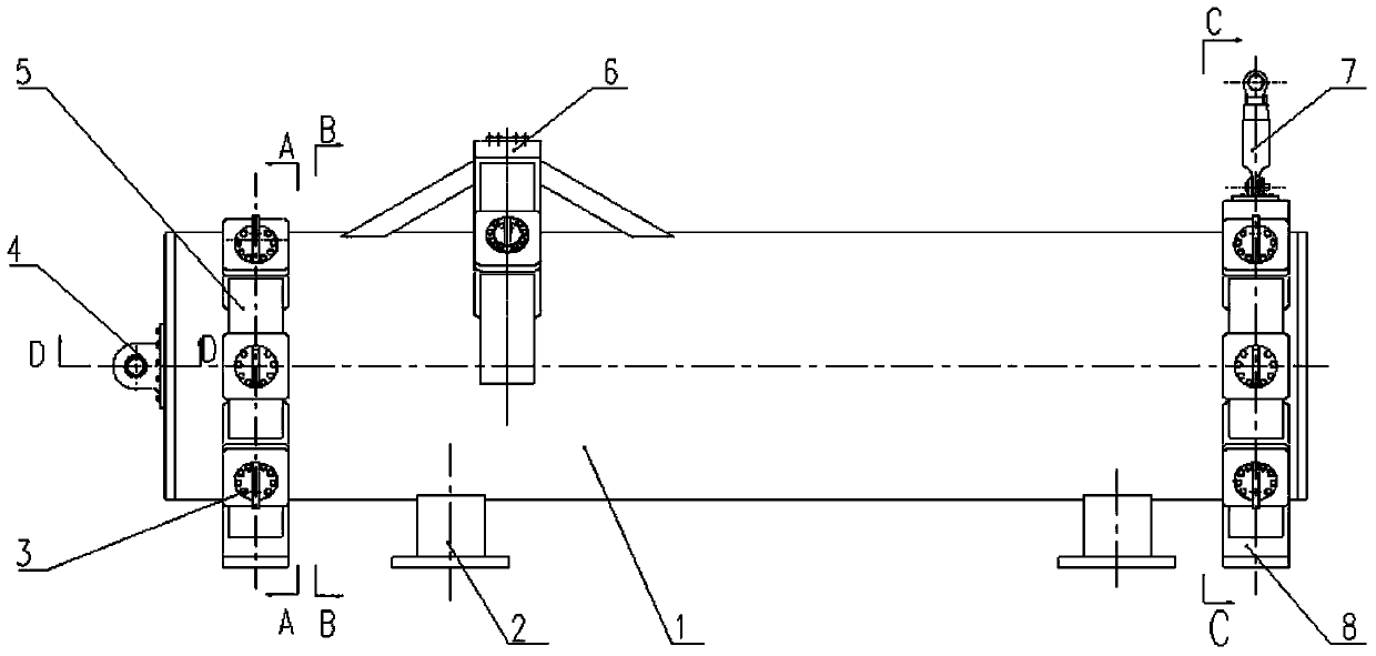
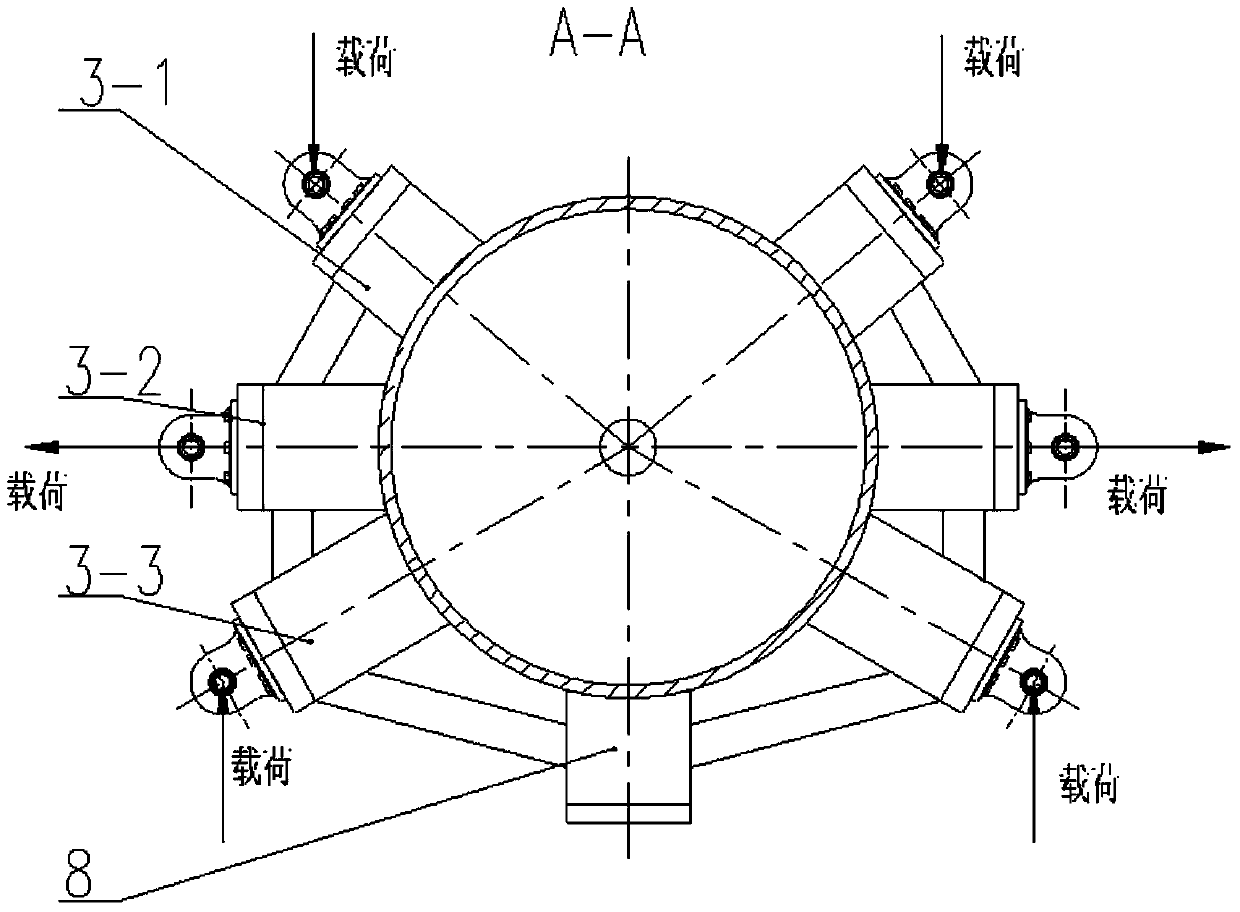
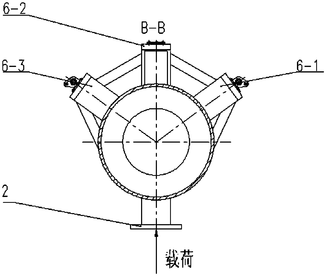
[0025] In this embodiment, the engine replacement equipment for the static test of the aircraft wing includes an engine simulation casing composed of a cylinder body 1, a front cover plate welded on the cylinder body, and a rear cover plate, and is fixedly arranged on the cylinder body radial direction. Two sets of transverse bearing joints 3 on both ends of the cylinder, axial bearing joints 4 fixedly arranged on the front cover plate along the axial direction of the cylinder, fixedly arranged on the upward loading platform 2 under the cylinder, and fixedly arranged on the top of the cylinder for For the suspension device 6 that suspends the replacement equipment under the wing of the aircraft, both the lateral bearing joint and the axial bearing joint are designed with a hinge connection structure with the load applying device.

[0026] The two sets of transverse load-bearing joints fixedly arranged on the two ends of the cylinder along the radial direction of the cylinder bo...


PUM


Abstract

The invention provides motor substitution equipment for the static force test of an airplane wing. The motor substitution equipment comprises a motor simulation shell formed by a drum body, a front cover plate and a rear cover plate, horizontal bearing joints arranged on two ends of the drum body along the radial direction of the drum body, an axial bearing joint fixedly arranged on the front cover plate along the axial direction of the drum body, an upward loading platform fixedly arranged below the drum body, and a suspension device fixedly arranged above the drum body for suspending the substitution equipment below the airplane wing; a structure in hinge connection with a load applying device is arranged at each of the horizontal bearing joints and the axial bearing joint; each of the horizontal bearing joints fixedly arranged on the two ends of the drum body along the radial direction of the drum body comprises two first bearing joints symmetrically arranged at two sides of the vertical bisecting surface of the drum body for bearing a vertical downward load, two second bearing joints for bearing a horizontal outward load and two third bearing joints for bearing a vertical upward load. Substitution equipment is adopted for performing the static force test of the airplane wing, and the test risk and cost can be reduced.

Description

technical field [0001] The invention relates to the technical field of the static strength test of the whole aircraft, in particular to the static strength test of the aircraft wing, in particular to an alternative device which can replace the engine in the static test of the aircraft wing. Background technique [0002] In the process of aircraft development, the static strength test of the aircraft wing is an important part of the static strength test of the overall aircraft strength. The theoretical strength of the aircraft wing is verified by the static strength test of the aircraft wing. This experiment needs to simulate the most severe state in the flight load of the aircraft design, and the most severe state is usually not obtained through actual flight missions, and can only be simulated through ground tests. The experiment theoretically requires 4 real engines as loading sources to simulate the load transmitted from the engines to the wings of the aircraft during fli...

Claims


Application Information

Patent Timeline
Patent Type & Authority Applications(China)
IPC IPC(8): G01M13/00
Inventor 龙虹云刘建杜嘉陵孙洋张良孔雅婵邓家琛陈登勇
Owner CHENGDU ENGINE GROUP
Learn More