
Water pressure monitoring terminal system for firefighting sites

A technology for monitoring terminal and water pressure, applied in measuring devices, measuring fluid pressure, instruments, etc., can solve problems such as low efficiency, insufficient water pressure, interruption of water supply in the front field, etc., to improve combat efficiency, work efficiency, and reliable transmission. Effect

Inactive Publication Date: 2014-03-12
NO 50 RES INST OF CHINA ELECTRONICS TECH GRP
View PDF9 Cites 1 Cited by
  • Summary
  • Abstract
  • Description
  • Claims
  • Application Information

AI Technical Summary

Problems solved by technology

[0004] At present, in the actual fire fighting scene, the front field commander notifies the operator of the water pump truck by voice to provide the required water supply pressure, but the entire water supply line from the water pump truck to the water outlet nozzle in the front field lacks effective monitoring. The firefighters do not know whether the water pressure of the water nozzle meets the requirements, and the commander cannot keep abreast of the actual situation of each water outlet node
[0005] (2) The way to find the fault point of the water supply line is backward and the efficiency is low
[0006] In the process of on-site fire fighting, due to the bursting of the hose and external obstructions, etc., the water supply in the front field is often interrupted and the water pressure is insufficient.
At present, it is only possible to check the water supply lines one by one manually to find problems, which is very inefficient.

Method used


Image

  • Water pressure monitoring terminal system for firefighting sites

Examples


Embodiment Construction

[0033] The following is a detailed description of the embodiments of the present invention: this embodiment is implemented on the premise of the technical solution of the present invention, and provides detailed implementation methods and specific operation processes. It should be noted that those skilled in the art can make several modifications and improvements without departing from the concept of the present invention, and these all belong to the protection scope of the present invention.

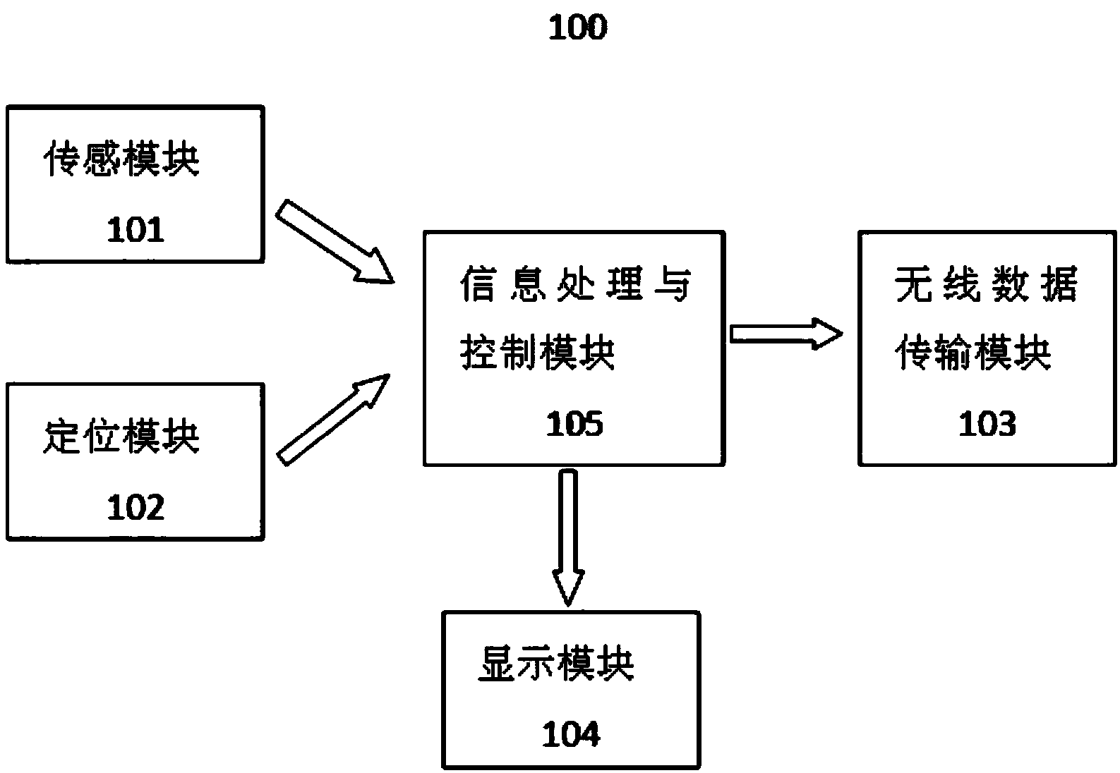
[0034] Such as figure 1 As shown, this embodiment provides a water pressure monitoring terminal system for firefighting, including a sensing module, a positioning module, an information processing and control module, a display module, and a wireless data transmission module. The sensing module and the positioning module are respectively connected to the The information processing is connected with the control module, and the information processing and control module are respectively con...


PUM


Abstract

The invention provides a water pressure monitoring terminal system for firefighting sites. The water pressure monitoring terminal system comprises a sensing module, a positioning module, an information processing and controlling module, a displaying module and a wireless data transmission module. The sensing module and the positioning module are connected with the information processing and controlling module respectively. The information processing and controlling module is connected with the displaying module and the wireless data transmission module respectively. The water pressure monitoring terminal system utilizing the digitization technology has functions such as real-time water pressure monitoring, real-time positioning and real-time automatic warning, is applicable to strict application environments of the firefighting sites through the reinforcing design, and can be connected with fire hoses and manifolds quickly through standard interfaces without damaging existing fire hose and manifold structures; by the water pressure monitoring terminal system, water pressure information of water supply circuit nodes of the firefighting sites can be known quickly in real time, reference information is provided for on-site management, conditions, causing abnormal water pressure, such as breakage of the fire hoses can be found timely, and working efficiency of on-site firefighting can be improved.

Description

technical field [0001] The invention relates to the technical field of fire-fighting on-site monitoring systems, in particular to a fire-fighting on-site water pressure monitoring terminal system. Background technique [0002] At present, water supply guarantee is a very important content in the actual firefighting scene, which has a direct impact on the smooth progress of fire fighting work. However, there are some problems in the current guarantee means, mainly including: [0003] (1) Lack of monitoring of water supply pressure [0004] At present, in the actual fire fighting scene, the front field commander notifies the operator of the water pump truck by voice to provide the required water supply pressure, but the entire water supply line from the water pump truck to the front field water nozzle lacks effective monitoring. The firefighters do not know whether the water pressure of the water nozzle meets the requirements, and the commander cannot keep abreast of the actu...

Claims


Application Information

Patent Timeline
Patent Type & Authority Applications(China)
IPC IPC(8): G01L19/12
Inventor 马歆磊纪华郭俊岑
Owner NO 50 RES INST OF CHINA ELECTRONICS TECH GRP
Learn More