
Control circuit enabling switch voltage stabilization circuit to keep high efficiency within wide current range

A technology for controlling circuits and current ranges, applied in the field of switching voltage regulator circuits, can solve problems such as switch drive current loss, and achieve the effect of reducing noise emissions and reducing the possibility

Inactive Publication Date: 2014-03-05
SUZHOU BATELAB MICROELECTRONICS
View PDF3 Cites 13 Cited by
  • Summary
  • Abstract
  • Description
  • Claims
  • Application Information

AI Technical Summary

Problems solved by technology

These losses include, quiescent current losses of the control circuit in the regulator, switching losses, switch drive current losses, inductor / transformer winding and core losses

Method used


Image

  • Control circuit enabling switch voltage stabilization circuit to keep high efficiency within wide current range
  • Control circuit enabling switch voltage stabilization circuit to keep high efficiency within wide current range
  • Control circuit enabling switch voltage stabilization circuit to keep high efficiency within wide current range

Examples


Embodiment Construction

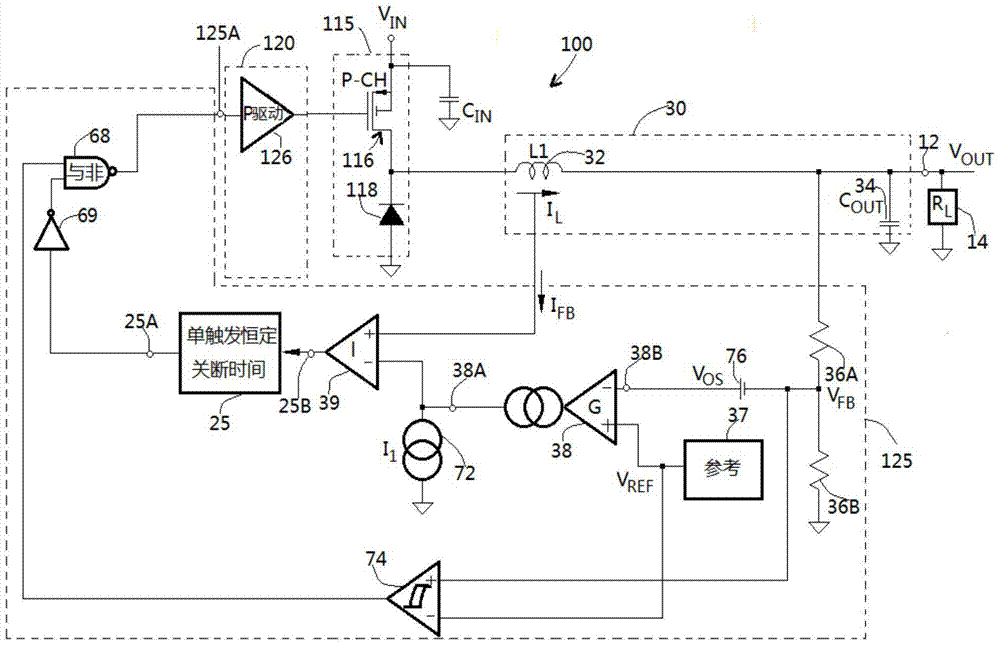
[0029] figure 1 It is a typical switching regulator circuit of traditional technology, which adopts a push-pull switch with voltage drop configuration.

[0030] refer to figure 1 , circuit 10 is used to provide an adjustable DC output voltage V at terminal 12 OUT , used to drive a load 14, which may be a portable or notebook computer or other battery-powered systems. circuit 10 from an unregulated voltage source V IN to obtain power, the voltage source V IN coupled to terminal 14 (eg, a 12 volt battery). The circuit 10 includes a push-pull switch 15 , a drive circuit 20 , an output circuit 30 and a control circuit 35 .

[0031] The driving circuit 20 is used to drive the push-pull switch 15, which includes two synchronous switching power MOS transistors 16 (p-channel) and 17 (n-channel), which are overlapped and connected in series with the power supply V IN and the ground. The push-pull switch 15 in the drive circuit 20 is a device commonly referred to as a "bridge". ...


PUM


Abstract

The invention provides a control circuit enabling a switch voltage stabilization circuit to keep the high efficiency within a wide current range. The circuit for controlling a switch stabilizer comprises a switch (1) which comprises an output end comprising one or more switch transistors (2) and is used for providing a current for a load with a steady voltage, wherein the load comprises an output capacitor. When the voltage of the output end can basically keep the steady voltage of the output capacitor, a control signal can be generated according to the circuit and a method, and therefore the switch transistors can be stopped. According to the circuit and method, the efficiency of the stabilization circuit can be improved especially under the condition that the average current is low.

Description

Technical field: [0001] The invention relates to a switch voltage stabilizing circuit. More particularly, the present invention relates to a control circuit and method for maintaining high efficiency of a switching regulator circuit within a wide current range. Background technique: [0002] The purpose of a voltage regulator is to provide a predetermined constant output voltage to the load. In general, there are two different types of regulators: series regulators and switching regulators. [0003] Series regulators use a pass element (eg, a power transistor) coupled in series with a load to control the voltage drop across the pass element to regulate the voltage across the load. In contrast, switching regulators employ a switch (eg, a power transistor) coupled in series or in parallel with the load. The regulator turns on and off the switch to regulate the power to the load. This switching regulator uses an inductive energy storage element to convert the switching curr...

Claims


Application Information

Patent Timeline
IPC IPC(8): H02M1/08H02M1/088H02M3/155
Inventor 不公告发明人
Owner SUZHOU BATELAB MICROELECTRONICS
Learn More