Vehicle pneumatic tyre

A technology for pneumatic tires and vehicles, applied in vehicle parts, tire parts, tire treads/tread patterns, etc., can solve problems such as movable instability, avoid edge involvement effect, large edge length, reduce noise The effect of emissions

Active Publication Date: 2015-05-13
CONTINENTAL REIFEN DEUTSCHLAND GMBH
View PDF7 Cites 2 Cited by
  • Summary
  • Abstract
  • Description
  • Claims
  • Application Information

AI Technical Summary

Problems solved by technology

The corresponding block is cut apart and divided into a larger number of block parts by the implementation and arrangement of these narrow grooves or cuts, which makes the associated block soft, movable and unstable

Method used


Image

  • Vehicle pneumatic tyre
  • Vehicle pneumatic tyre
  • Vehicle pneumatic tyre

Examples


Embodiment Construction

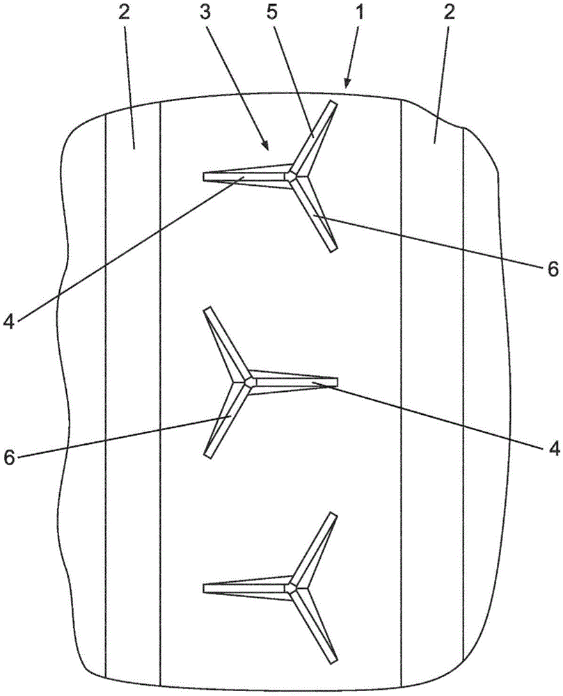
[0027] figure 1 A tread band 1 of a tread pattern of a pneumatic vehicle tire for passenger cars is schematically shown in a radial configuration. exist figure 1 The tread strips 1 shown in may have the usual widths for tread strips in the tread of passenger car tires in the order of 18 mm to 36 mm and each have a wide circumferential groove running straight around in the circumferential direction 2 defines that further ribs, not shown and indicated in detail and which may be, for example, tread bands and / or rows of blocks, are connected laterally or axially to the circumferential groove . In the following description, "depth", "tread depth" and similar expressions are respectively understood as the distance measured in radial direction between the surface of the tread 1 and the mentioned position (e.g. a groove base). distance between. The deepest position of these circumferential grooves 2 lies in the maximum tread depth set for the tread in question, which is usually ch...


PUM


Abstract

Pneumatic vehicle tyre with a tread which are divided by circumferential grooves (2) and by tread lugs extending in the circumferential direction, at least one profile strip (1, 1', 1 ") being part of said profiles. In the profile strip (1, 1', 1 "), respectively three grooves (4, 5, 6, 4', 4 ", 5 ", 6 ") having a width of 0.8 mm to 1.5 mm form a groove group (3, 3', 3 "). Said grooves (4, 5, 6, 4', 4 ", 5 ", 6 ") form stars, starting from a recessed central region (7), and at least two grooves (5, 6, 5 ", 6 ") of the groove group (3, 3', 3 ") end within the profile strip (1, 1', 1") and a groove (4, 4', 4 ") extends axially or essentially in the axial direction of the running strip.

Description

technical field [0001] The invention relates to a pneumatic tire for vehicles with a tread demarcated by circumferential grooves and ribs running around in the circumferential direction, the ribs being associated with at least one tread band, wherein the tread A plurality of grooves having a width of 0.8 mm to 1.5 mm are formed in the belt. Background technique [0002] Pneumatic vehicle tires with such a tread are known in various embodiments. Common are, for example, treads with rows of blocks with blocks separated from each other by transverse grooves and / or with a tread band in which the grooves terminate from a The circumferential grooves extend into these tread bands. Known from JP-A-01047603 is a tread having a tread pattern consisting of rows of blocks, wherein narrow grooves or cuts in each block extend substantially radially from the A central depression of the block extends out to the block edges, where it merges into the grooves delimiting the block. The corr...

Claims


Application Information

Patent Timeline
Patent Type & Authority Applications(China)
IPC IPC(8): B60C11/03
CPCB60C11/032B60C11/0306B60C2011/0341
Inventor 乌尔里希·贝尔
Owner CONTINENTAL REIFEN DEUTSCHLAND GMBH
Why Eureka
Try Eureka